Driving method of display device

a display device and driving method technology, applied in the direction of 3d-image rendering, instruments, computing, etc., can solve the problems of reducing crosstalk between consecutive frames, affecting the display effect, so as to reduce crosstalk between the right and left images, and reduce the effect of display defects

Active Publication Date: 2012-05-31
SEMICON ENERGY LAB CO LTD
View PDF7 Cites 11 Cited by
  • Summary
  • Abstract
  • Description
  • Claims
  • Application Information

AI Technical Summary

Benefits of technology

[0040]According to one embodiment of the present invention, display defects such as crosstalk between consecutive frames can be reduced in consecutive frame periods.
[0041]Further, according to one embodiment of the present invention, crosstalk between the right and left images can be reduced when the right and left images are switched and a stereoscopic image is displayed.

Problems solved by technology

The driving by a field sequential system has a unique problem of a display defect such as color breakup (also referred to as color break).

Method used


Image

  • Driving method of display device
  • Driving method of display device
  • Driving method of display device

Examples


embodiment 1

[0064]In this embodiment, a method for driving a display device in one embodiment of the present invention will be described.

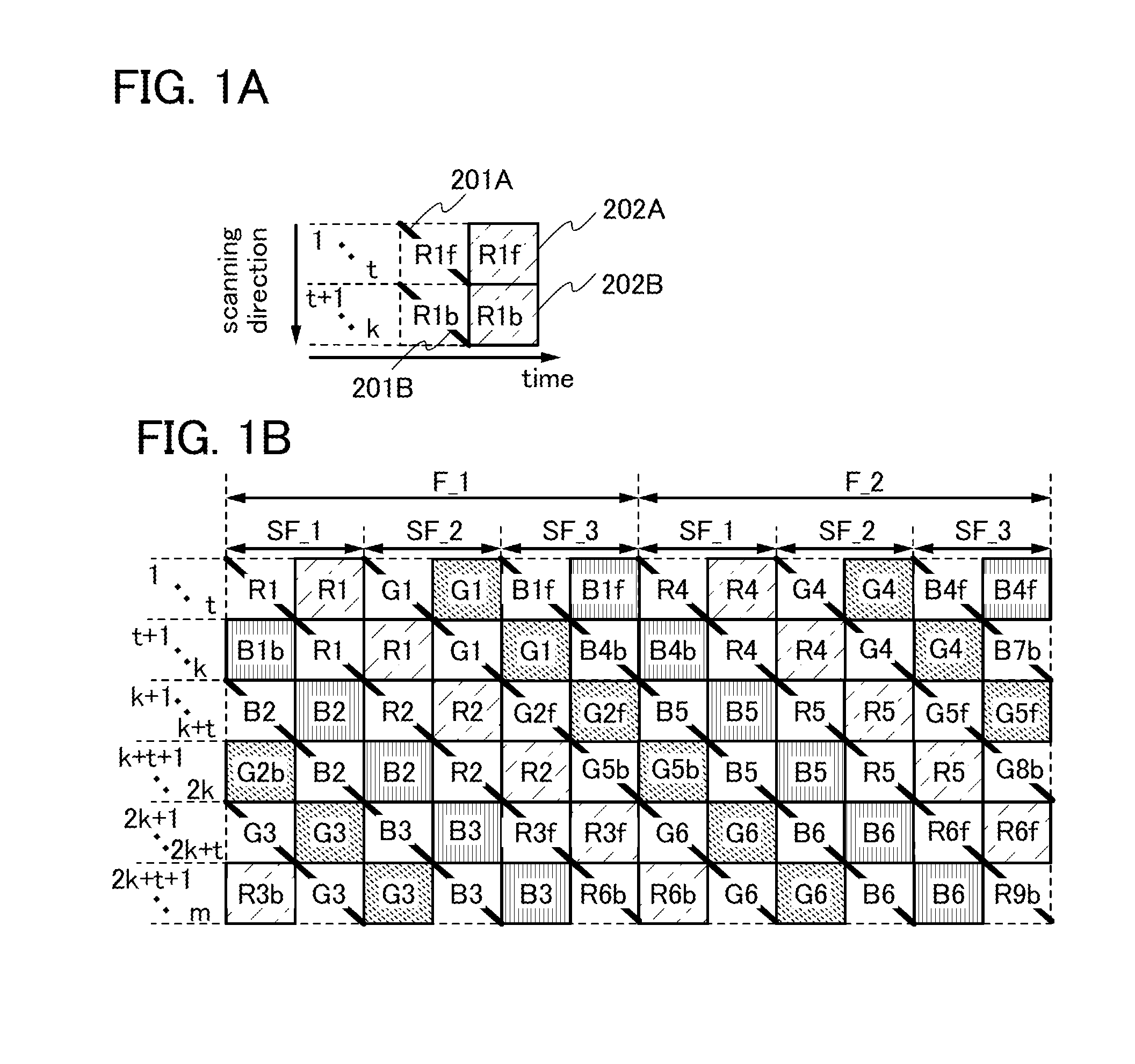
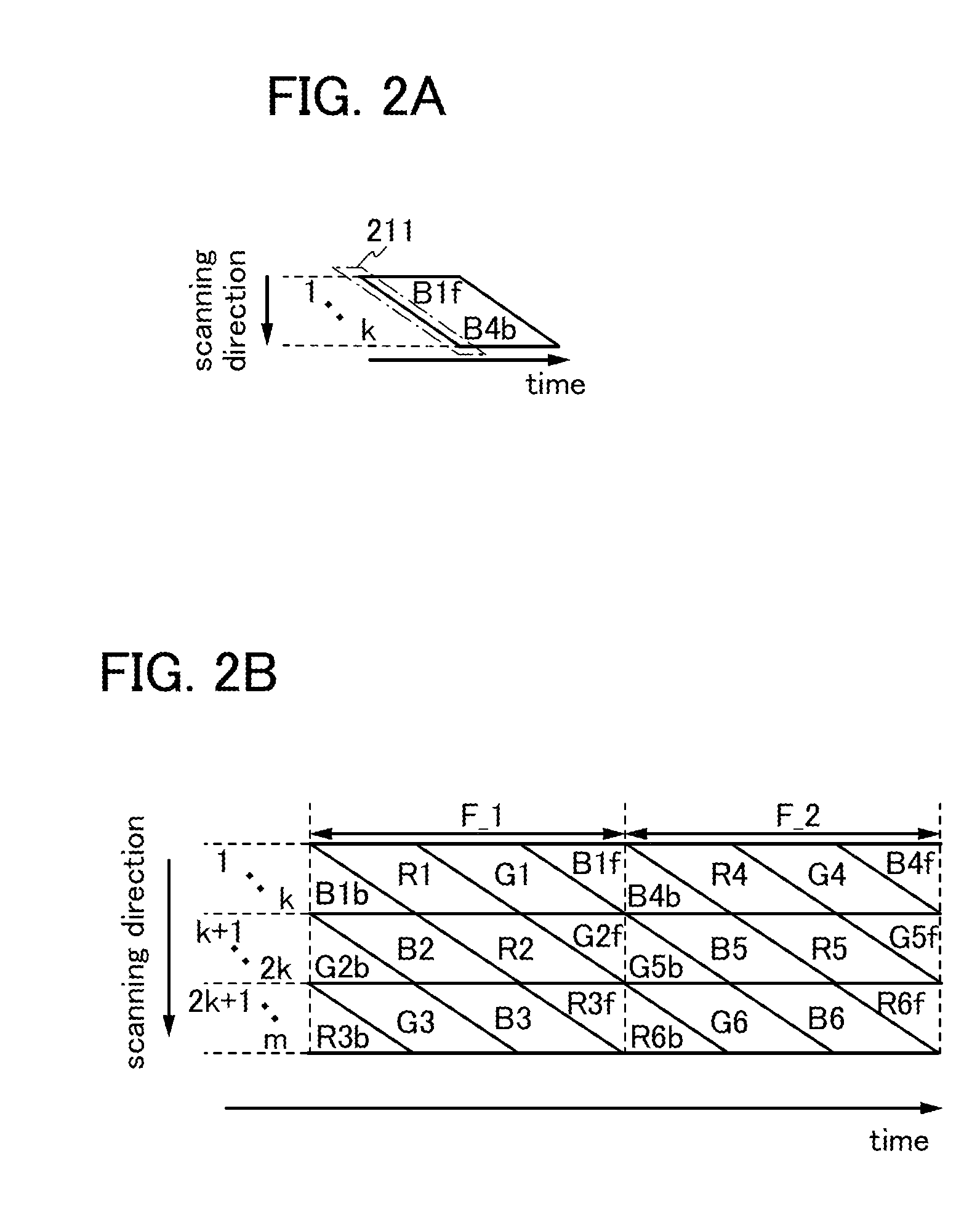
[0065]FIG. 1A is a schematic view of writing of image signals and lighting of light sources corresponding to regions to which the image signals have been written. In FIG. 1A, selection signals are sequentially supplied to a plurality of scan lines (also referred to as gate lines) in a direction (scanning direction) where the plurality of scan lines is provided, so that a state of writing of image signals of signal lines (also referred to as data lines) to pixels and a state of lighting of the light sources are illustrated. In FIG. 1A, a state in which writing of the image signals to the pixels of the first to t-th rows (I is a natural number smaller than k) and the pixels of the (t+1)-th to k-th rows and lighting of the light sources are performed as time passes is illustrated.

[0066]Although light sources of three colors (R (red), G (green), and B (blue)) are ...

embodiment 2

[0107]In this embodiment, a driving method of a liquid crystal display device in which a black image is inserted between frames in the structure described in Embodiment 1 will be described.

[0108]FIG. 3A is a schematic view of writing of image signals and the sum of a response period of liquid crystals and a lighting period of light sources corresponding to regions to which the image signals are written. FIG. 3A illustrates a state in which, when selection signals are sequentially supplies to scan lines of first to i-th rows in a direction (scanning direction) where a plurality of scan lines (also referred to as gate lines) is provided, image signals for displaying a black image are written to pixels of signal lines (also referred to as data lines), and a state of a non-lighting period of light sources.

[0109]In FIG. 3A, a heavy line 221 represents writing of the image signals for displaying a black image, and a region shown by an oblique hatching 222 represents the sum of a response ...

embodiment 3

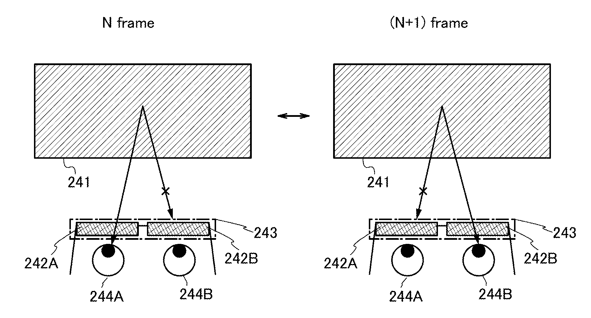
[0136]In this embodiment, a structure for seeing a stereoscopic image using any of the driving methods of a display device described in Embodiment 1 and Embodiment 2 will be described.

[0137]As illustrated in FIG. 5, an image for a left eye and an image for a right eye included in a display portion 241 of a display device in which any of the driving methods of a display device described in Embodiment 1 and Embodiment 2 is performed is seen using glasses 243 including a left eye shutter 242A and a right eye shutter 242B, so that different images can be seen with a left eye 244A and a right eye 244B.

[0138]In other words, as illustrated in FIG. 5, in an N frame (N is a natural number), light from the display portion, which enters the left eye 244A, is transmitted through the left eye shutter 242A and no light from the display portion, which enters the right eye 244B is transmitted through the right eye shutter 242B. In addition, in a (N+1) frame, no light from the display portion, which...


PUM


Abstract

An object is to reduce crosstalk between consecutive frame periods. The writing period of image signals to each pixel and the lighting period of light sources corresponding to the image signals in one frame period are rearranged so that the lighting period of the light sources corresponding to the image signals does not overlap with a previous frame period and the next frame period, and the image signals are written and the light sources corresponding to the image signals are on. Specifically, a display region is divided into a plurality of regions, and each of the plurality of regions is divided for rows in a first half and rows in a latter half. The image signals written to the rows in the latter half are written in the previous frame period, and the light sources corresponding to the image signals are on in the frame period.

Description

BACKGROUND OF THE INVENTION[0001]1. Field of the Invention[0002]The present invention relates to a driving method of a display device, in particular, a driving method of a liquid crystal display device using a liquid crystal element for a display element.[0003]2. Description of the Related Art[0004]Display devices typified by liquid crystal display devices, ranging from large display devices such as television receivers to small display devices such as mobile phones, have been spreading. From now on, products with higher added values will be needed and are being developed. In recent years, in view of increase in concern about global environment and improvement in convenience of mobile devices, development of display devices with low power consumption has attracted attention.[0005]As a display device with low power consumption, there is a display device which displays an image by a field sequential system (also referred to as a color sequential display method, a time-division display...

Claims


Application Information

Patent Timeline
Patent Type & Authority Applications(United States)
IPC IPC(8): G09G3/36G06T15/00
CPCG09G3/342G09G3/3677H04N13/0422G09G2320/0209H04N13/0497G09G2310/0235G09G2310/024H04N13/0438H04N13/324H04N13/341H04N13/398G02B30/24G09G3/2022G09G3/3648G09G3/3674
Inventor HIRAKATA, YOSHIHARU
Owner SEMICON ENERGY LAB CO LTD
Why Eureka
Try Eureka