
Nozzle Capable of Maximizing the Quantity of Movement Produced by a Two-Phase Flow Through the Relief of a Saturating Flow

Inactive Publication Date: 2012-05-31
ASSOC POUR LA RECH & LE DEV DES METHODES & PROCESSUS IND (ARMINES)
View PDF13 Cites 4 Cited by
  • Summary
  • Abstract
  • Description
  • Claims
  • Application Information

AI Technical Summary

Benefits of technology

[0050]The invention thus proposes mixing the vapor and liquid phases, thereby considerably increasing the momentum that is produced by the liquid / vapor two-phase flow coming from the expansion of the saturated liquid, as is explained below.
[0059]The invention thus makes it possible to mix in satisfactory manner the vapor and liquid phases of the primary flow and to entrain the secondary flow much more efficiently than is possible in ejectors of the state of the art. As a result, a real outlet pressure is obtained that is very close to the theoretical outlet pressure.
[0063]In a particular embodiment, the ejector of the invention includes a second mixer element, in part in the mixing chamber and in part in the diverging portion. This characteristic encourages mixing of the two-phase flow of the primary flow at the outlet of the nozzle with the secondary flow.

Problems solved by technology

In contrast, the use of ejectors or nozzles to expand saturated liquids remains marginal, since the appearance of a vapor phase puts a considerable limit on the quantity of momentum in the liquid / vapor two-phase flow after expansion.
Such bad performance has severely limited the development of two-phase turbines, with some people even believing that they are of no use, industrially.

Method used


Image

  • Nozzle Capable of Maximizing the Quantity of Movement Produced by a Two-Phase Flow Through the Relief of a Saturating Flow
  • Nozzle Capable of Maximizing the Quantity of Movement Produced by a Two-Phase Flow Through the Relief of a Saturating Flow
  • Nozzle Capable of Maximizing the Quantity of Movement Produced by a Two-Phase Flow Through the Relief of a Saturating Flow

Examples


Embodiment Construction

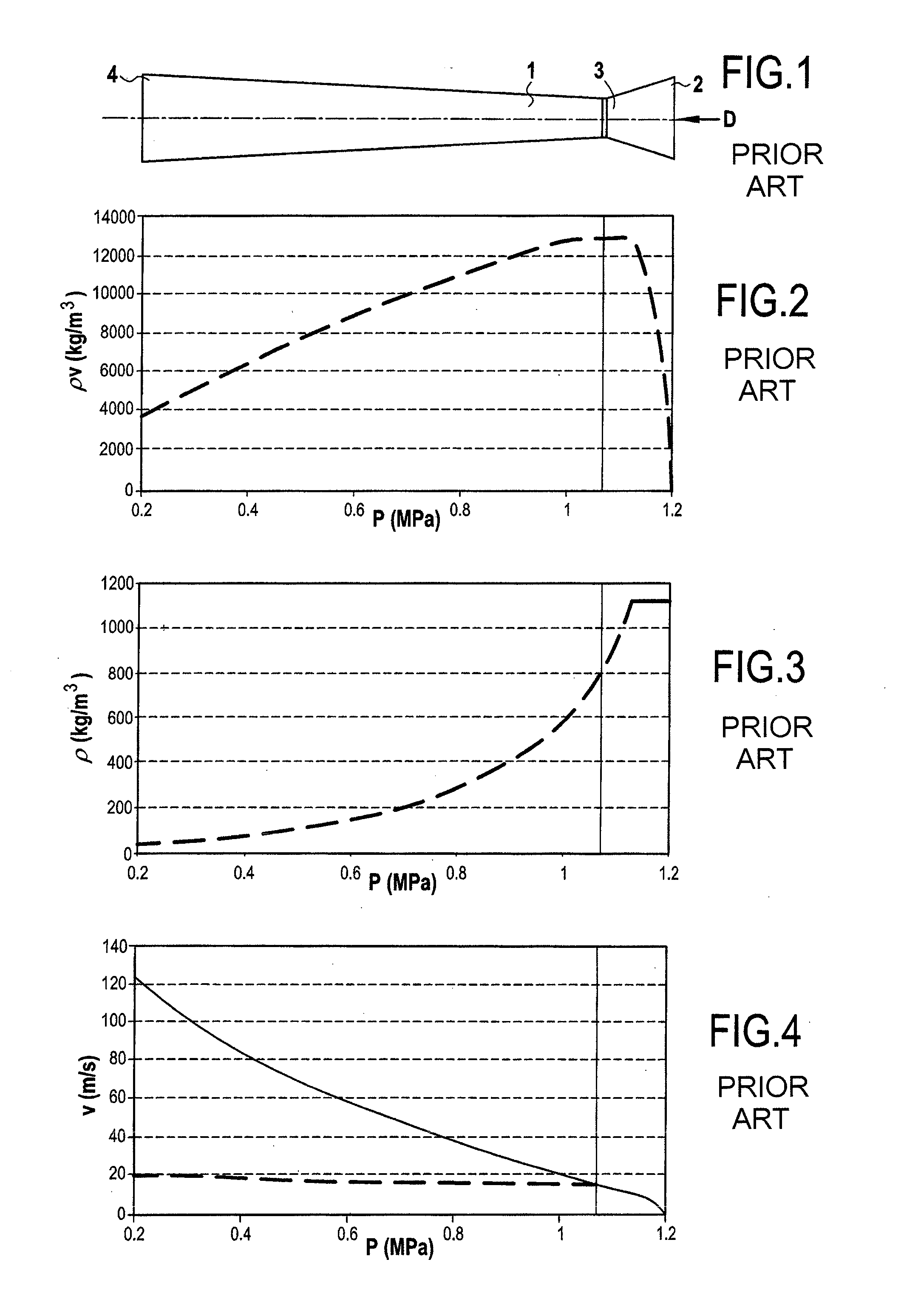
[0079]FIGS. 7A and 7B show a nozzle 10 in accordance with the invention.

[0080]It differs from the nozzle 1 of FIG. 1 in that it includes a mixer element 5 downstream from the throat 3, the mixer element being suitable for creating uniform mixing of the vapor and liquid phases in the moderately diverging portion 4, with this having the consequence of considerably increasing the momentum of the two-phase flow at the outlet from the diverging portion 4.

[0081]In the embodiment described herein, the moderately diverging portion 4 of the nozzle 10 in accordance with the invention is of a lightly flaring conical shape so as to maintain a mass flow rate that is constant during the acceleration of the two-phase flow.

[0082]In the embodiment shown herein, the mixer element 5 is constituted by a stationary helix, as shown in FIG. 8.

[0083]In FIG. 9, a continuous bold line shows the variation in the velocity V of the flow D as a function of pressure as it travels along the nozzle 10. This figure ...


PUM


Abstract

The nozzle (10) is suitable for expanding a saturated flow (D) and comprises a converging portion (2), a throat (3), a tube (4), and a mixer element (5) downstream from said throat (3) and suitable for mixing the vapor and liquid phases of the saturated flow.

Description

BACKGROUND OF THE INVENTION[0001]The invention lies in the field of ejectors and nozzles used as expansion members in turbines.[0002]In general, such devices are designed to transform pressure energy into kinetic energy, the kinetic energy then being used to produce work, e.g. to cause turbine blades or buckets to revolve, or with ejectors it is used to suck in a flow.[0003]Such devices are commonly used to expand vapor or liquids that are highly sub-cooled.[0004]In contrast, the use of ejectors or nozzles to expand saturated liquids remains marginal, since the appearance of a vapor phase puts a considerable limit on the quantity of momentum in the liquid / vapor two-phase flow after expansion.[0005]FIGS. 1 to 4 illustrate this phenomenon. FIG. 1 shows a nozzle 1 in accordance with the present state of the art. The nozzle 1 comprises a converging portion 2, a throat 3, and a diverging portion 4 of moderate angle. A flow of saturated liquid D enters the nozzle 1 via the converging port...

Claims


Application Information

Patent Timeline
IPC IPC(8): F01D1/34B05B1/00F01D1/18
CPCB05B1/3415F03B3/186Y02E10/226Y02E10/223F03B11/02Y02E10/20
Inventor BOU LAWZ KSAYER, ELIASCLODIC, DENIS
Owner ASSOC POUR LA RECH & LE DEV DES METHODES & PROCESSUS IND (ARMINES)
Learn More