Yaw bearing assembly and tower for wind turbine

a technology for wind turbines and bearing assemblies, which is applied in the direction of reaction engines, mechanical equipment, machines/engines, etc., can solve the problems of increasing load peaks, increasing the number and rows of bearing balls, and impractical and/or disproportionately expensive yaw bearings

Inactive Publication Date: 2012-05-31
GENERAL ELECTRIC CO
View PDF3 Cites 11 Cited by
  • Summary
  • Abstract
  • Description
  • Claims
  • Application Information

AI Technical Summary

Problems solved by technology

However, a yaw bearing of such increased size may be impractical and/or disproportionately expensive.
However, such increase in the number and rows of bearing balls may be prohibitively expensive.
Additionally, the use of a single

Method used


Image

  • Yaw bearing assembly and tower for wind turbine
  • Yaw bearing assembly and tower for wind turbine
  • Yaw bearing assembly and tower for wind turbine

Examples


Embodiment Construction

[0014]Reference now will be made in detail to embodiments of the invention, one or more examples of which are illustrated in the drawings. Each example is provided by way of explanation of the invention, not limitation of the invention. In fact, it will be apparent to those skilled in the art that various modifications and variations can be made in the present invention without departing from the scope or spirit of the invention. For instance, features illustrated or described as part of one embodiment can be used with another embodiment to yield a still further embodiment. Thus, it is intended that the present invention covers such modifications and variations as come within the scope of the appended claims and their equivalents.

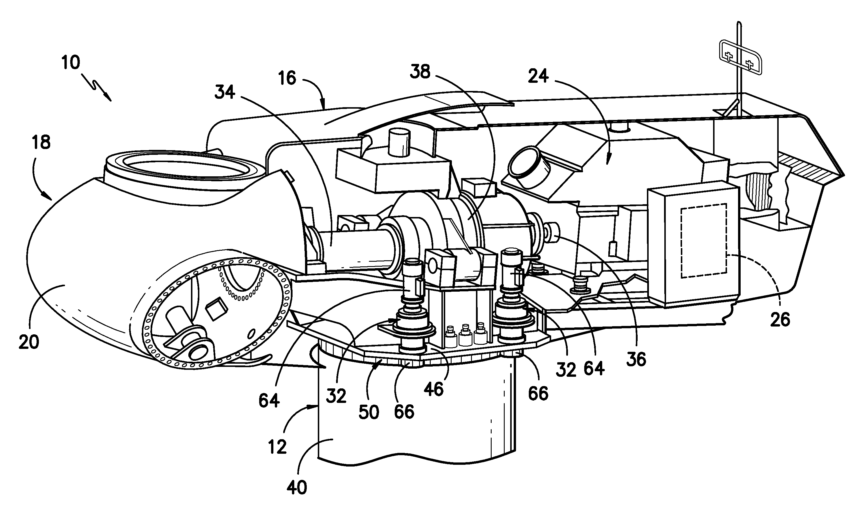
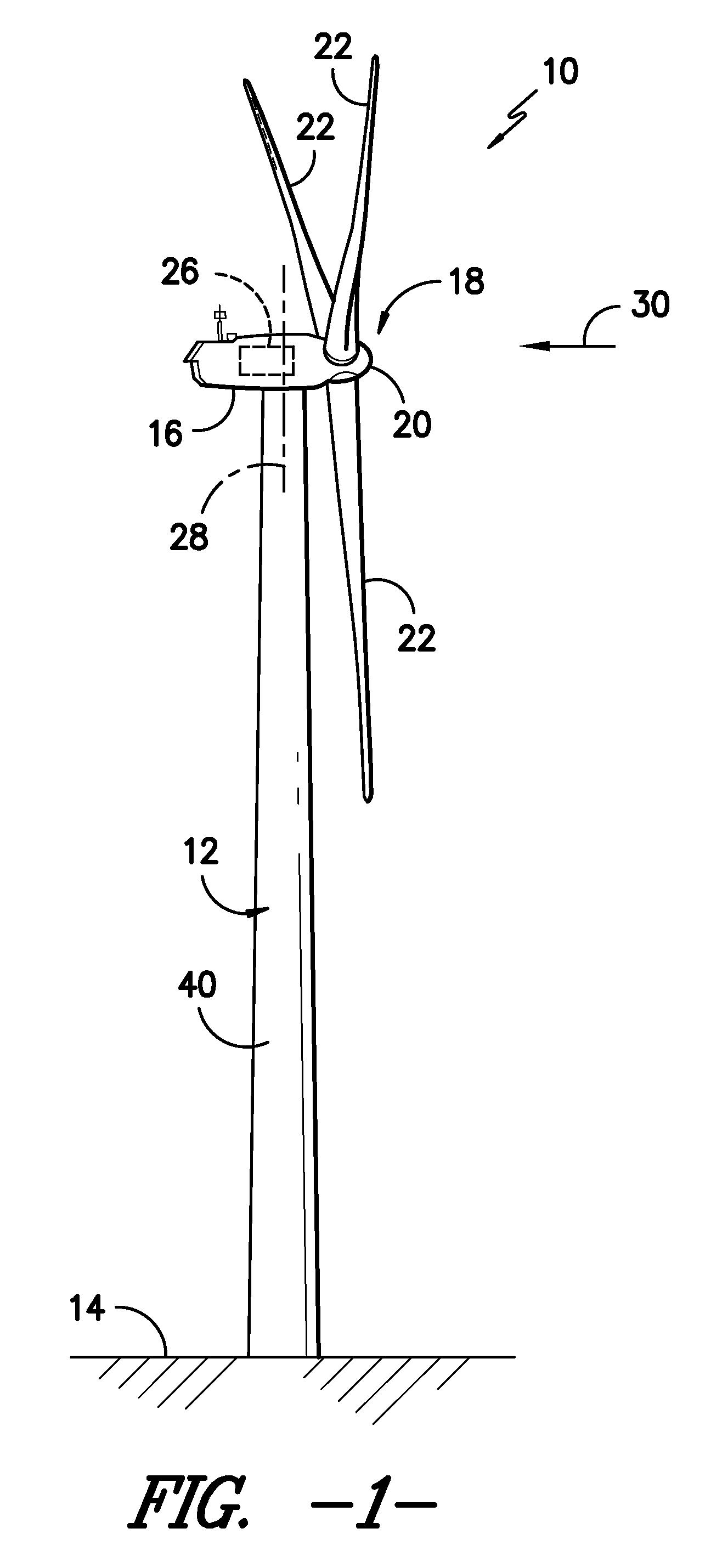
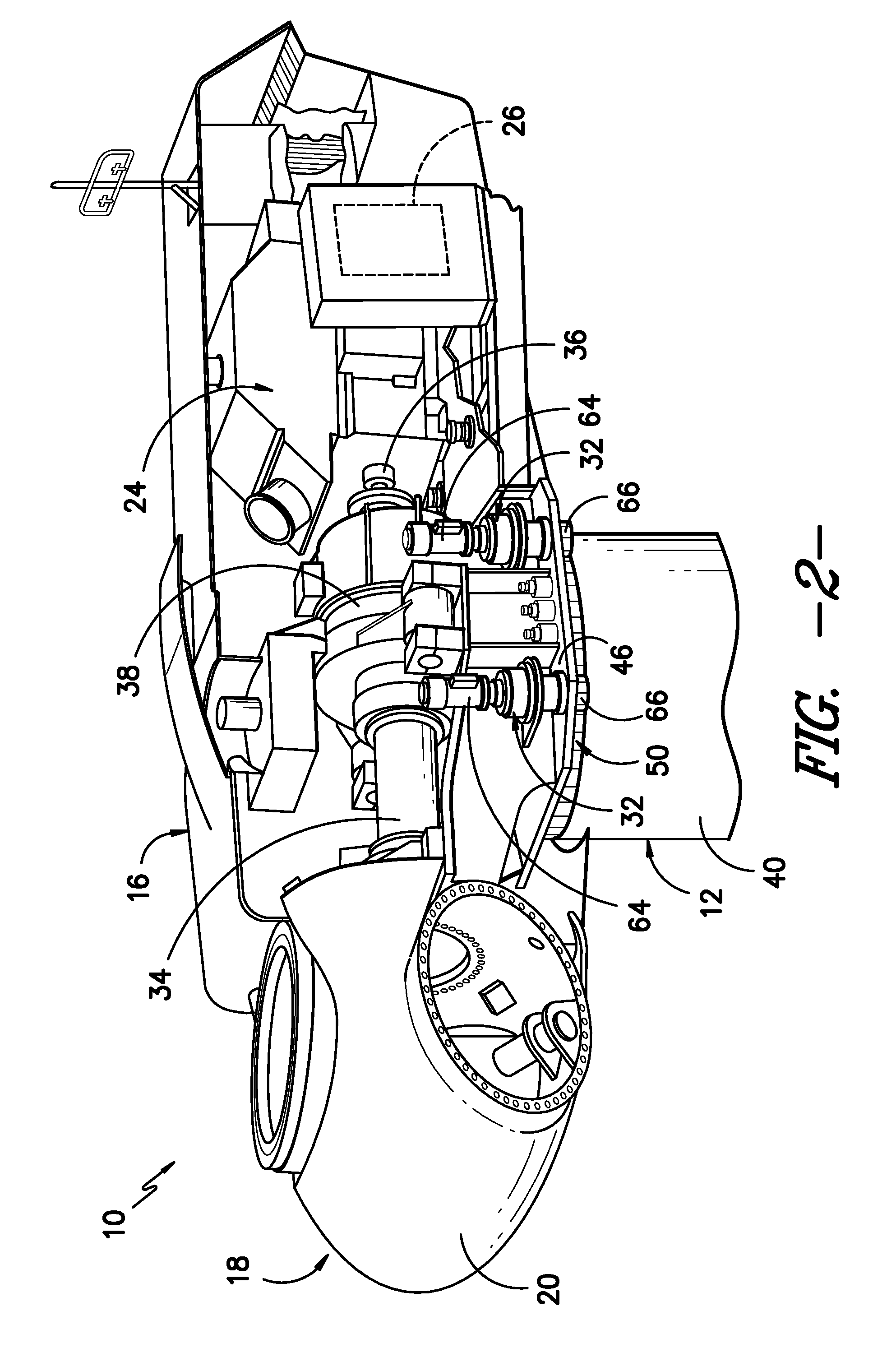
[0015]Referring to the drawings, FIG. 1 illustrates perspective view of one embodiment of a wind turbine 10. As shown, the wind turbine 10 includes a tower 12 extending from a support surface 14, a nacelle 16 mounted on the tower 12, and a rotor 18 coupled ...


PUM


Abstract

A tower for a wind turbine is disclosed. The tower includes an outer shell defining a yaw axis and a main frame for a nacelle. The tower further includes a first yaw bearing and a second yaw bearing each connecting the outer shell and the main frame. The first yaw bearing and the second yaw bearing are spaced apart from each other along the yaw axis and each rotatable about the yaw axis.

Description

FIELD OF THE INVENTION[0001]The present subject matter relates generally to yaw bearing assemblies and towers for wind turbines and, more particularly, to yaw bearing assemblies and towers including more than one yaw bearing.BACKGROUND OF THE INVENTION[0002]Generally, a wind turbine includes a tower, a nacelle mounted on the tower, and a rotor coupled to the nacelle. The rotor typically includes a rotatable hub and a plurality of rotor blades coupled to and extending outwardly from the hub. Each rotor blade may be spaced about the hub so as to facilitate rotating the rotor to enable kinetic energy to be transferred from the wind into usable mechanical energy, and subsequently, electrical energy.[0003]To properly orient the rotor blades relative to the direction of the wind, wind turbines typically include one or more yaw drive mechanisms configured to engage a single yaw bearing for rotating the nacelle relative to the tower. As wind turbines continue to increase in size, this yaw b...

Claims


Application Information

Patent Timeline
IPC IPC(8): F03D11/04F03D1/00F03D11/00
CPCF03D7/0204F03D11/0008F05B2240/40Y02E10/723F16C2360/31Y02E10/722F05B2240/50F03D80/70F16C19/54Y02E10/72
Inventor MADGE, JAMES HENRYMINADEO, ADAM DANIEL
Owner GENERAL ELECTRIC CO
Why Eureka
Try Eureka