Method of polishing a substrate using a polishing tape having fixed abrasive

Active Publication Date: 2012-05-31
EBARA CORP
View PDF12 Cites 9 Cited by
  • Summary
  • Abstract
  • Description
  • Claims
  • Application Information

AI Technical Summary

Benefits of technology

[0024]When the molecules, having a structure that causes the steric hindrance, are adsorbed onto the lower layer, etching of the lower layer is substantially stopped. As a result, the polishing rate of the lower layer is reduced greatly, compared with the polishing rate of the upper film formed on the lower layer. Therefore, the polishing method according to the present invention can remove only the upper film, while leav

Problems solved by technology

However, use of such a polishing tape may roughen a surface of the substrate as a result of contact with the fixed abrasive.
However, the loose abrasive grains may adhere to semiconductor devices on the substrate due to the rotation of the substrate.
Moreover, use of such a powerful cleanin

Method used


Image

  • Method of polishing a substrate using a polishing tape having fixed abrasive
  • Method of polishing a substrate using a polishing tape having fixed abrasive
  • Method of polishing a substrate using a polishing tape having fixed abrasive

Examples


Example

[0045]Embodiments of the present invention will be described below with reference to the drawings.

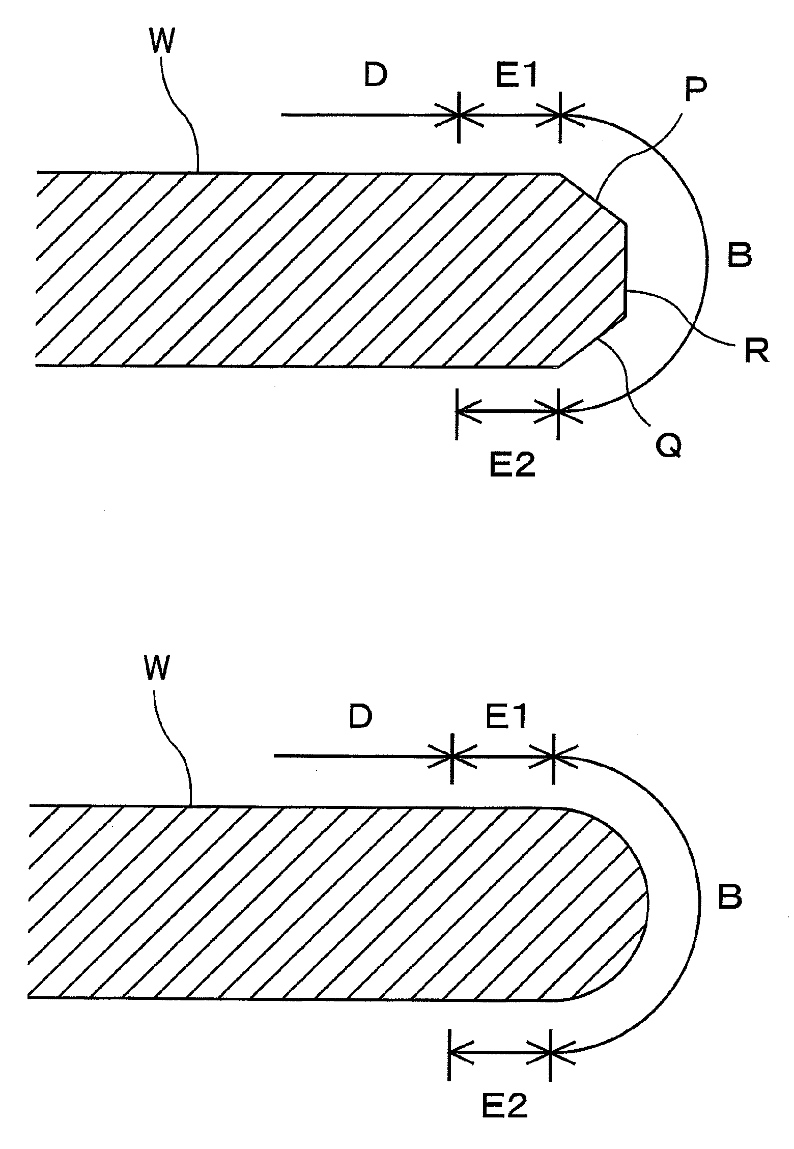
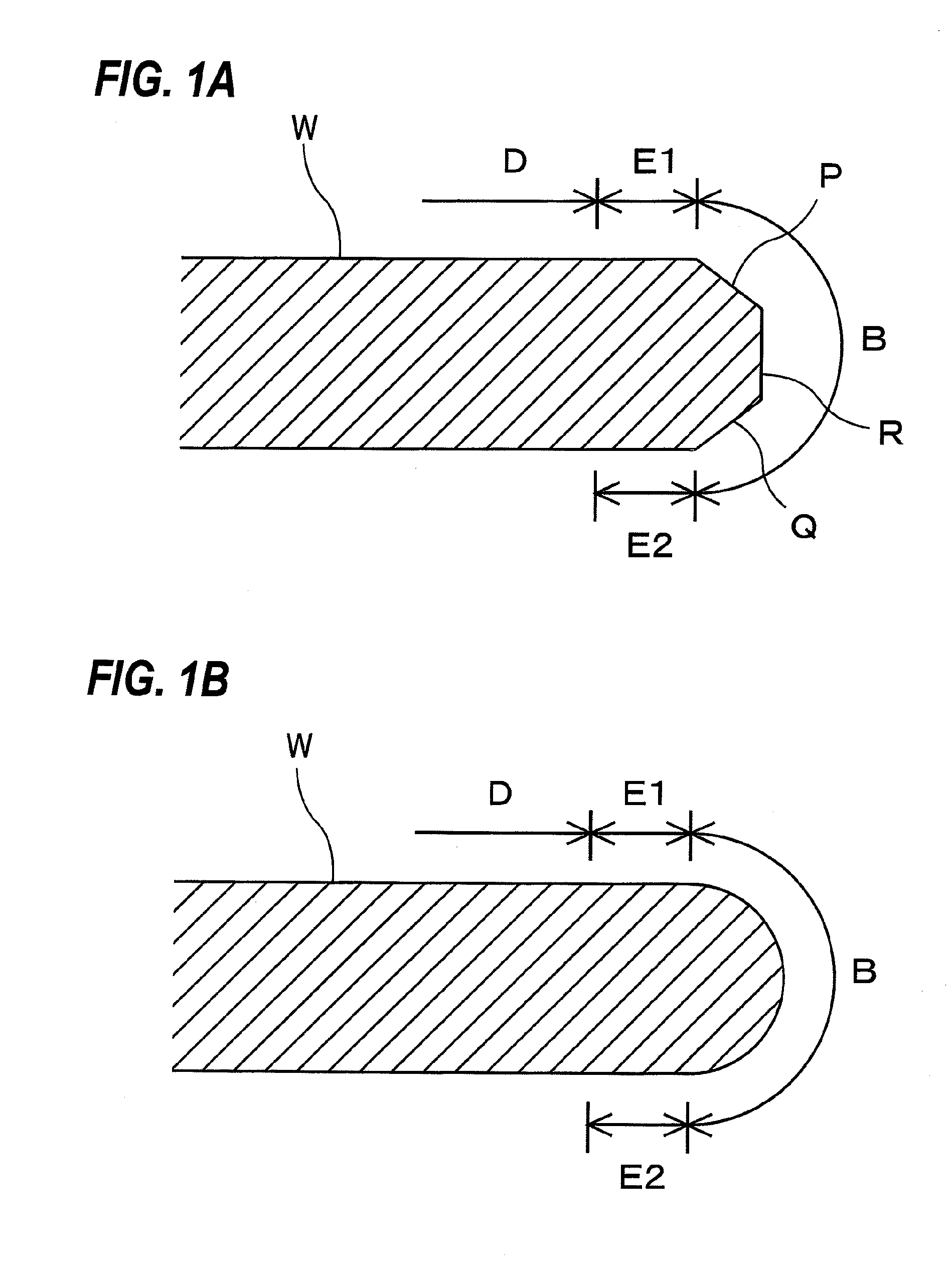
[0046]In this specification, a peripheral portion of a substrate is defined as a region including a bevel portion and near-edge portions. FIG. 1A and FIG. 1B are enlarged cross-sectional views each showing the peripheral portion of the substrate. More specifically, FIG. 1A shows a cross-sectional view of a so-called straight-type substrate, and FIG. 1B shows a so-called round-type substrate.

[0047]In the substrate W shown in FIG. 1A, the bevel portion is a portion B that is constituted by an upper slope (an upper bevel portion) P, a lower slope (a lower bevel portion) Q, and a side portion (an apex) R, all of which are located in a circumferential surface of the substrate W. In the substrate W shown in FIG. 1B, a bevel portion is a portion B having a curved cross section with a certain curvature and located in a circumferential surface of the substrate W. The near-edge portions are regio...


PUM

PropertyMeasurementUnit
Forceaaaaaaaaaa
Abrasiveaaaaaaaaaa
Tensionaaaaaaaaaa

Abstract

A method of polishing a peripheral portion of a substrate is provided. This method includes: causing sliding contact between the peripheral portion of the substrate and a polishing tape; and supplying a polishing liquid onto the polishing tape contacting the peripheral portion of the substrate. The polishing tape includes a base tape and a fixed abrasive formed on the base tape, and the polishing liquid is an alkaline polishing liquid containing an alkaline chemical and an additive including molecules that cause steric hindrance.

Description

BACKGROUND OF THE INVENTION[0001]1. Field of the Invention[0002]The present invention is related to a method of polishing a substrate using a polishing tape having a fixed abrasive, and more particularly to a method of polishing a peripheral portion of a substrate using the polishing tape.[0003]2. Description of the Related Art[0004]In semiconductor device fabrication, various materials are deposited in the form of film on a wafer repeatedly to constitute a multilayer structure. This multilayer structure is formed not only on a surface of the wafer, but also on a peripheral portion of the wafer. The peripheral portion of the wafer is a region which is not used for products. It is necessary to remove a film on the peripheral portion, because the film on the peripheral portion would be peeled off during transporting of the wafer and would then adhere to device regions on the wafer, causing a lowered yield. Thus, in order to remove the film on the peripheral portion of the wafer, polis...

Claims


Application Information

Patent Timeline
IPC IPC(8): B24B1/00
CPCB24B21/002B24B9/065B24B37/02
Inventor NAKANISHI, MASAYUKISEKI, MASAYAKODERA, KENJI
Owner EBARA CORP
Why Eureka
Try Eureka