Polishing Tool for Finishing Optically Effective Surfaces on Spectacle Lenses in Particular

Active Publication Date: 2012-05-31
SATISLOH AG
View PDF10 Cites 8 Cited by
  • Summary
  • Abstract
  • Description
  • Claims
  • Application Information

AI Technical Summary

Benefits of technology

[0005]The present invention has the object of providing a polishing tool for automatic tool change, the interface of which with the tool spindle is, with simple and economic construction, more functionally reliable and is not exposed to rapid wear under the action of the polishing agent.ILLUSTRATION OF THE INVENTION
[0008]In this regard, a significant element of the invention is the use of a retaining ring of simple construction and the double allocation of function thereto, specifically on the one hand as a detent element and on the other hand as a sealing element. By virtue of the arrangement in accordance with the invention the polishing agent used cannot penetrate through the gap between the wall surface of the interior space and the mount of the tool spindle to reach the entrainer elements and the entrainer counter-elements, so that wear caused by polishing agent cannot occur at that location.

Problems solved by technology

The known solutions for the interface between tool spindle and base body of the polishing tool are not satisfactory, because they are exposed to a high degree of wear due to sprayed polishing agent.
Due to the chemical and mechanical action of the polishing agent the interface is therefore exposed to an extreme level of wear during processing by polishing.
The elements thereof serving for centering, detenting and torque transmission therefore wear out very quickly and no longer fulfill their function, which makes automatic tool change at least very difficult, if not impossible.

Method used


Image

  • Polishing Tool for Finishing Optically Effective Surfaces on Spectacle Lenses in Particular
  • Polishing Tool for Finishing Optically Effective Surfaces on Spectacle Lenses in Particular
  • Polishing Tool for Finishing Optically Effective Surfaces on Spectacle Lenses in Particular

Examples


Embodiment Construction

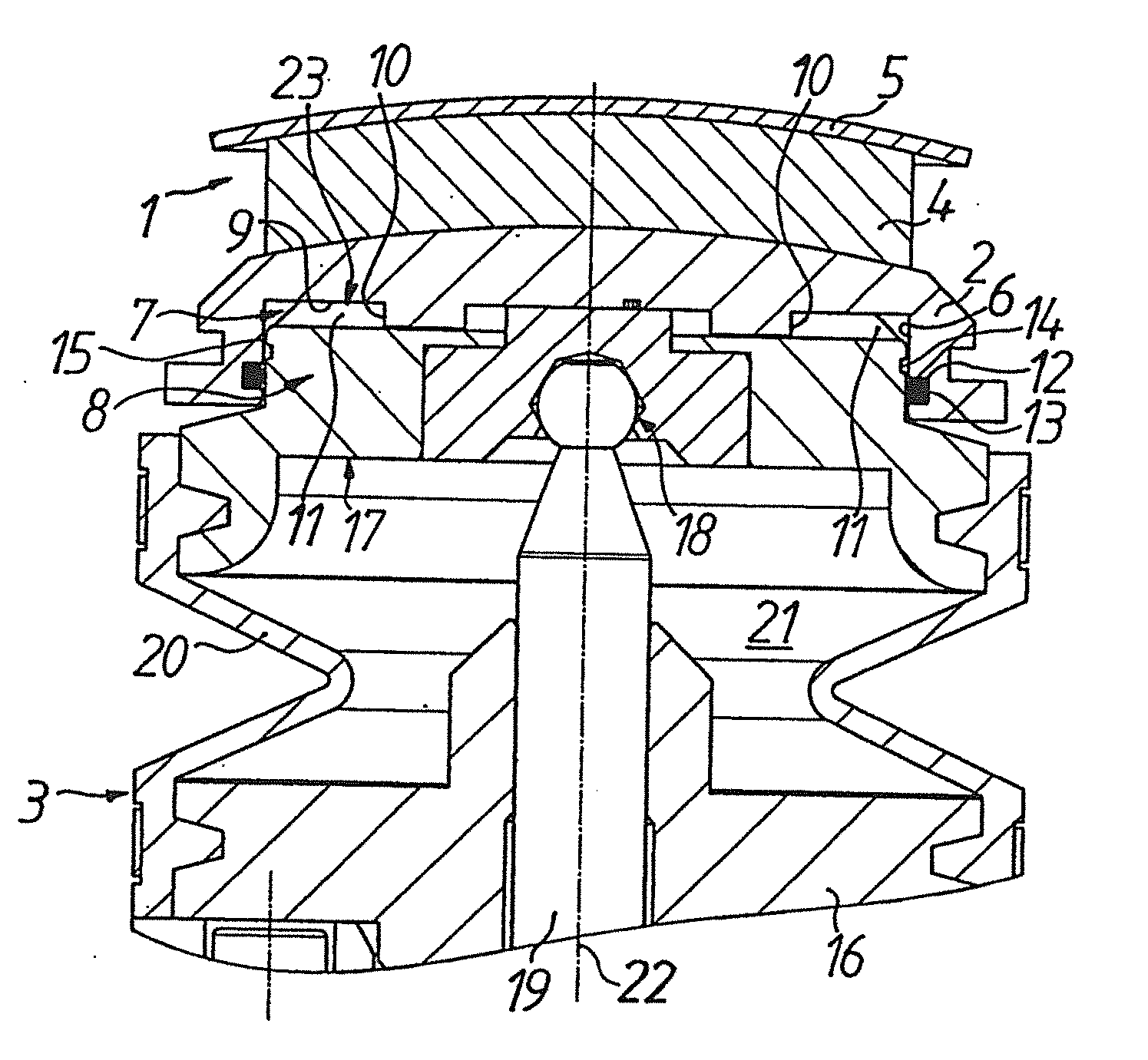
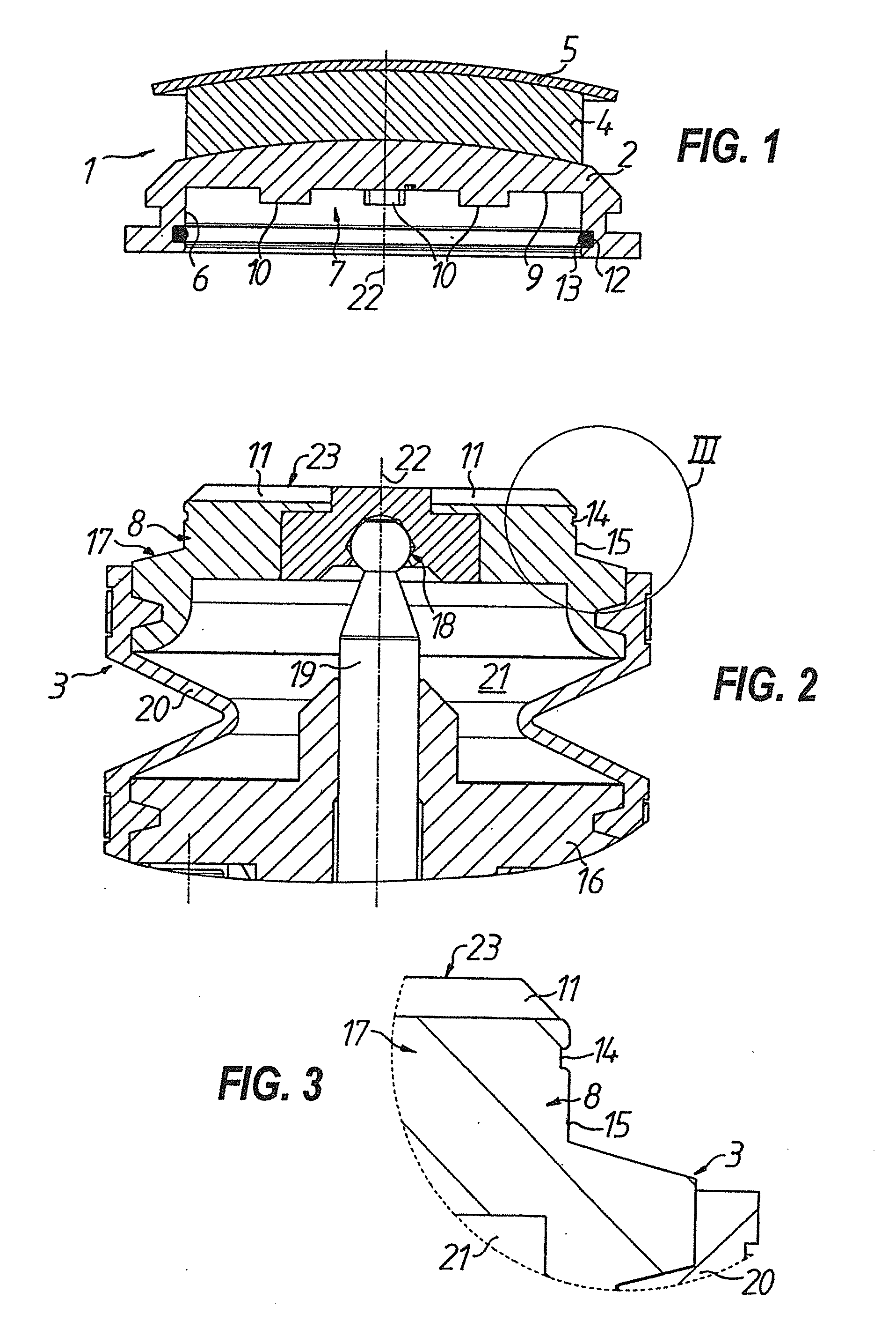
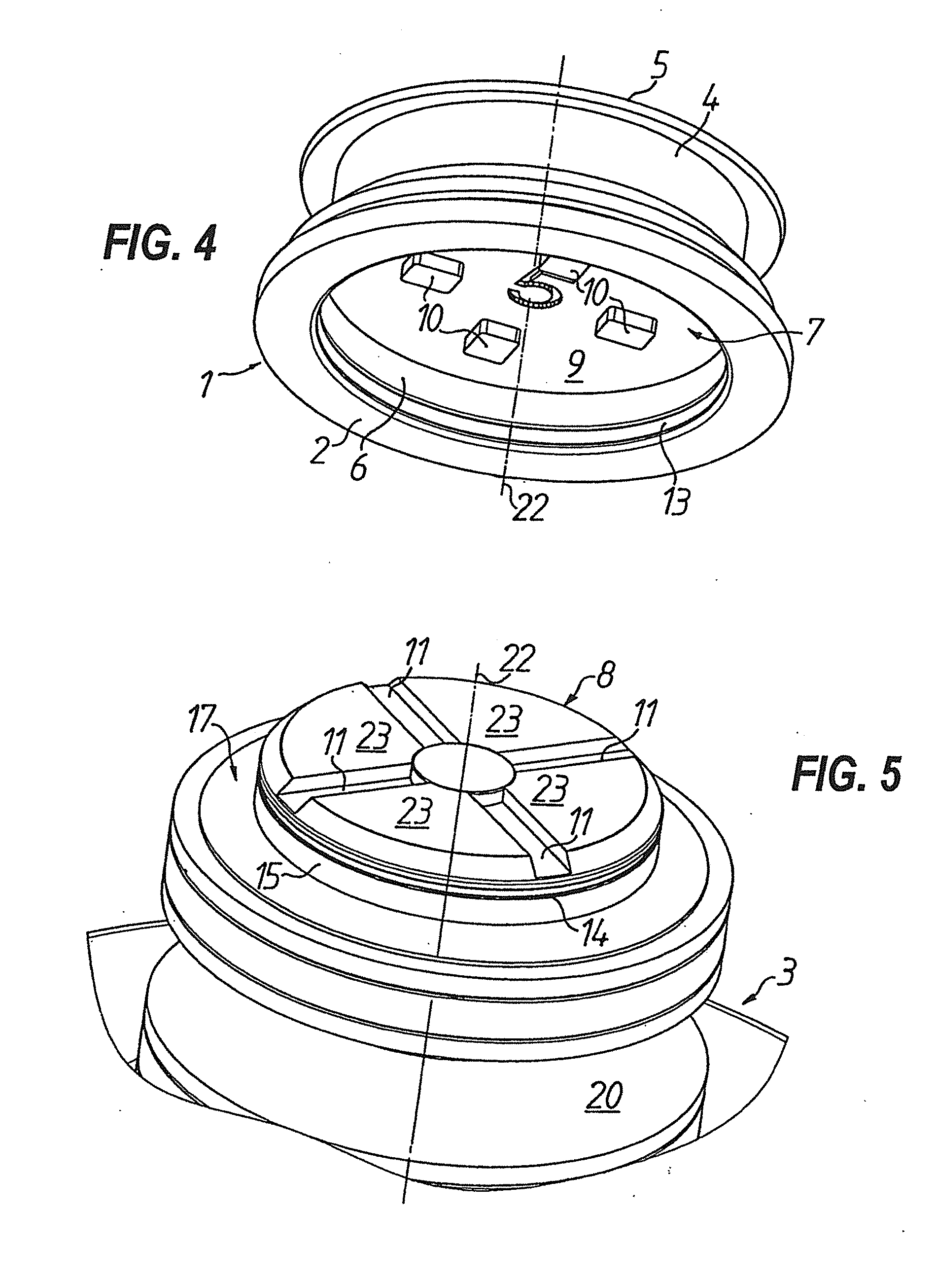
[0026]As apparent from the drawings, a flexible polishing tool 1 comprises a rotationally symmetrical base body 2 which can be mounted in a manner still to be described on the tool spindle 3 of a processing machine, the spindle being illustrated broken away in FIGS. 2, 3, 5 to 8 and 10. The polishing tool 1 serves for finishing of optically effective surfaces of, in particular, spectacle lenses (not illustrated). Provided at the outer side, i.e. the side remote from the tool spindle 3, of the base body 2 is a processing section which in the illustrated embodiment comprises an intermediate layer 4, which is fastened to the base body 2 and is softer in comparison with the base body 2, and a polishing agent support 5 resting on the intermediate layer 4. This construction of the polishing tool is sufficiently well known and therefore does not require further explanation here.

[0027]At its inner side, i.e. at its side facing the tool spindle 3, the base body 2 has an interior space 7 whic...


PUM


Abstract

The proposed polishing tool has a base body with an open interior space with which the polishing tool can be slidably fitted onto a holder of a tool spindle, initially as far as a latching position. A retaining ring placed in an annular groove of the interior space engages in a counter-groove of the holder. The polishing tool can then be slid further onto the holder under the polishing work pressure, until, under the simultaneous action of torque, driver elements of the base body engage in driver counter-elements of the holder for transmitting rotary movement. At least in the latter relative position between the polishing tool and tool spindle, the retaining ring provides a seal against penetration of the abrasive polishing agent.

Description

TECHNICAL FIELD[0001]The invention relates to a polishing tool for finishing optically effective surfaces of, in particular, spectacle lenses, comprising a base or support body provided at the outer surface thereof with a processing section which can comprise an intermediate layer, which is softer by comparison with the base body and which rests on a polishing agent support.PRIOR ART[0002]Polishing tools of that kind are used particularly in production according to prescription of spectacle lenses in large batch numbers and are already state of the art in different forms of embodiment (see, for example, EP-A-1 473 116, DE-A-10 2005 010 583, EP-A-2 014 412). With automatic polishing devices either individual lenses or lens pairs are removed completely automatically from prescription boxes, polished, subjected to preliminary cleaning and thereafter deposited back in the prescription boxes. During the polishing process the flexible polishing tools adapt to the surface of the lens to be...

Claims


Application Information

Patent Timeline
IPC IPC(8): B24B13/02B24D13/14B24B41/06
CPCB24B13/02B24D13/147B24B41/066B24B13/01B24B45/00F02B23/066F02B23/0663F02B75/282F02M61/14Y02T10/12B24B41/06B24D13/14
Inventor SCHAFER, HOLGERWALLENDORF, STEFFEN
Owner SATISLOH AG
Why Eureka
Try Eureka