Medical image processing apparatus method and program

a technology of medical image and apparatus, applied in the field of medical image processing techniques, can solve the problems of imposing additional work on the user, reducing the efficiency of diagnosis, and long observation time, so as to reduce the time period for observation, reduce work and operation, and reduce the sense of incongruity

Active Publication Date: 2012-05-31
FUJIFILM CORP
View PDF2 Cites 18 Cited by
  • Summary
  • Abstract
  • Description
  • Claims
  • Application Information

AI Technical Summary

Benefits of technology

[0037]According to the present invention, when a virtual endoscopic image viewed from a viewpoint on a given observation path is generated, the position of a wall region of the tubular structure present in a local observation direction at the viewpoint and in the vicinity of the local observation direction is identified based on the three-dimensional medical image. Further, a global observation direction at the viewpoint is estimated based on a positional relationship between the viewpoint and the wall region. Further, a visual range of the virtual endoscopic image is determined in such a manner that image information about a region located in the global observation direction with respect to the viewpoint is represented at a central part of the virtual endoscopic image. Therefore, the central region of the tubular structure is displayed at a central part of the virtual endoscopic image not only for positions in the vicinity of the viewpoint but also for positions away from the viewpoint. Accordingly, it is possible to generate a virtual endoscopic image in which the central region of the tubular structure appears in a manner similar to a real endoscopic image even at a curved region of the tubular structure. Therefore, it is possible to reduce a sense of incongruity felt by a user (observer) with respect to the visual range of the virtual endoscopic image. Further, it is possible to reduce the work and operation for changing the visual range. Further, it is possible to reduce a time period for observation, and to improve the efficiency of diagnosis.

Problems solved by technology

However, such an operation imposes an additional work on the user.
Consequently, an observation time becomes long, and the efficiency of diagnosis becomes lower.

Method used


Image

  • Medical image processing apparatus method and program
  • Medical image processing apparatus method and program
  • Medical image processing apparatus method and program

Examples


Embodiment Construction

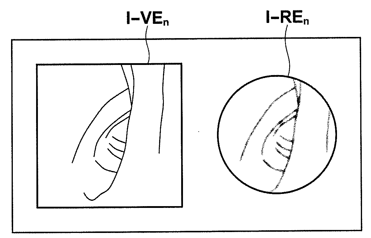
[0054]Hereinafter, a medical image diagnosis system into which a medical image processing apparatus according to an embodiment of the present invention has been introduced will be described by using, as an example, large intestine analysis processing for a virtual endoscope examination. In the virtual endoscope examination, while a viewpoint is moved along an observation path (center line) in the large intestine, virtual endoscopic images at the viewpoints are sequentially observed based on a three-dimensional medical image of the abdomen of a patient obtained by multi-slice CT.

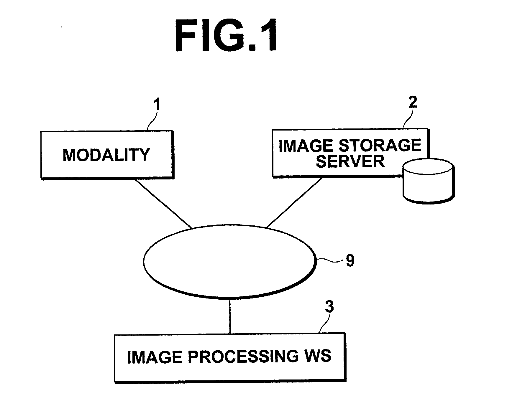
[0055]FIG. 1 is a schematic diagram illustrating the hardware configuration of the medical image diagnosis system. As illustrated in FIG. 1, the system includes a modality 1, an image storage server 2, and an image processing workstation 3, which are connected to each other through a network 9 in such a manner that they can communicate with each other.

[0056]The modality 1 performs radiography on the abdomen (...


PUM


Abstract

An observation path setting unit sets an observation path. A viewpoint setting and changing unit sets a viewpoint on the observation path. When a virtual endoscopic image viewed from the viewpoint is generated, a visual range determination unit identifies, based on a three-dimensional medical image, the position of a wall region of the tubular structure in a local observation direction at the viewpoint that has been set by the viewpoint setting and changing unit and in the vicinity of the local observation direction. The visual range determination unit estimates, based on a positional relationship between the viewpoint and the wall region, a global observation direction at the viewpoint, and determines a visual range of the virtual endoscopic image in such a manner that image information about a region located in the global observation direction with respect to the viewpoint is represented at a central part of the virtual endoscopic image.

Description

BACKGROUND OF THE INVENTION[0001]1. Field of the Invention[0002]The present invention relates to medical image processing techniques for generating a virtual endoscopic image from a three-dimensional medical image representing a tubular structure of a subject to be examined.[0003]2. Description of the Related Art[0004]In recent years, modalities such as MDCT (multidetector computed tomography) advanced, and high-quality three-dimensional (3D) medical images representing a subject to be examined became obtainable. As such 3D medical images are obtainable, medical image processing techniques for generating pseudo-3D images are being developed. An example of such techniques is a virtual endoscopic display method. In the virtual endoscopic display method, an image resembling an endoscopic image, which is obtained by imaging the inside of a tubular organ, is generated from plural two-dimensional tomographic images obtained by CT (computed tomography) (hereinafter, the image resembling a ...

Claims


Application Information

Patent Timeline
Patent Type & Authority Applications(United States)
IPC IPC(8): A61B1/04G06K9/00
CPCG06T2210/41G06T19/003
Inventor ITAI, YOSHINORI
Owner FUJIFILM CORP
Why Eureka
Try Eureka