Control apparatus for automatic stop of engine
a technology of control apparatus and automatic stop, which is applied in the direction of engine starters, machines/engines, instruments, etc., can solve the problems of engine not being able to automatically stop, engine cannot be automatically stopped, and the fuel saving benefit of the engine may be degraded, so as to achieve the effect of reducing the fuel saving benefit of the engine and further improving the fuel saving benefit of the idle stop control
- Summary
- Abstract
- Description
- Claims
- Application Information
AI Technical Summary
Benefits of technology
Problems solved by technology
Method used
Image
Examples
first embodiment
[0081]Hereinafter, referring to the accompanying drawings, a control apparatus, which is according to a first exemplary embodiment of the present invention and is applied to an on-vehicle engine system, will now be described.
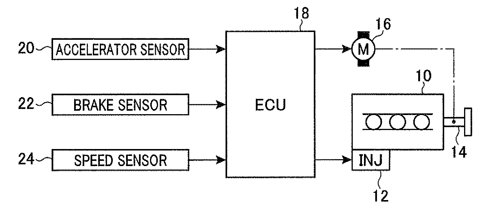
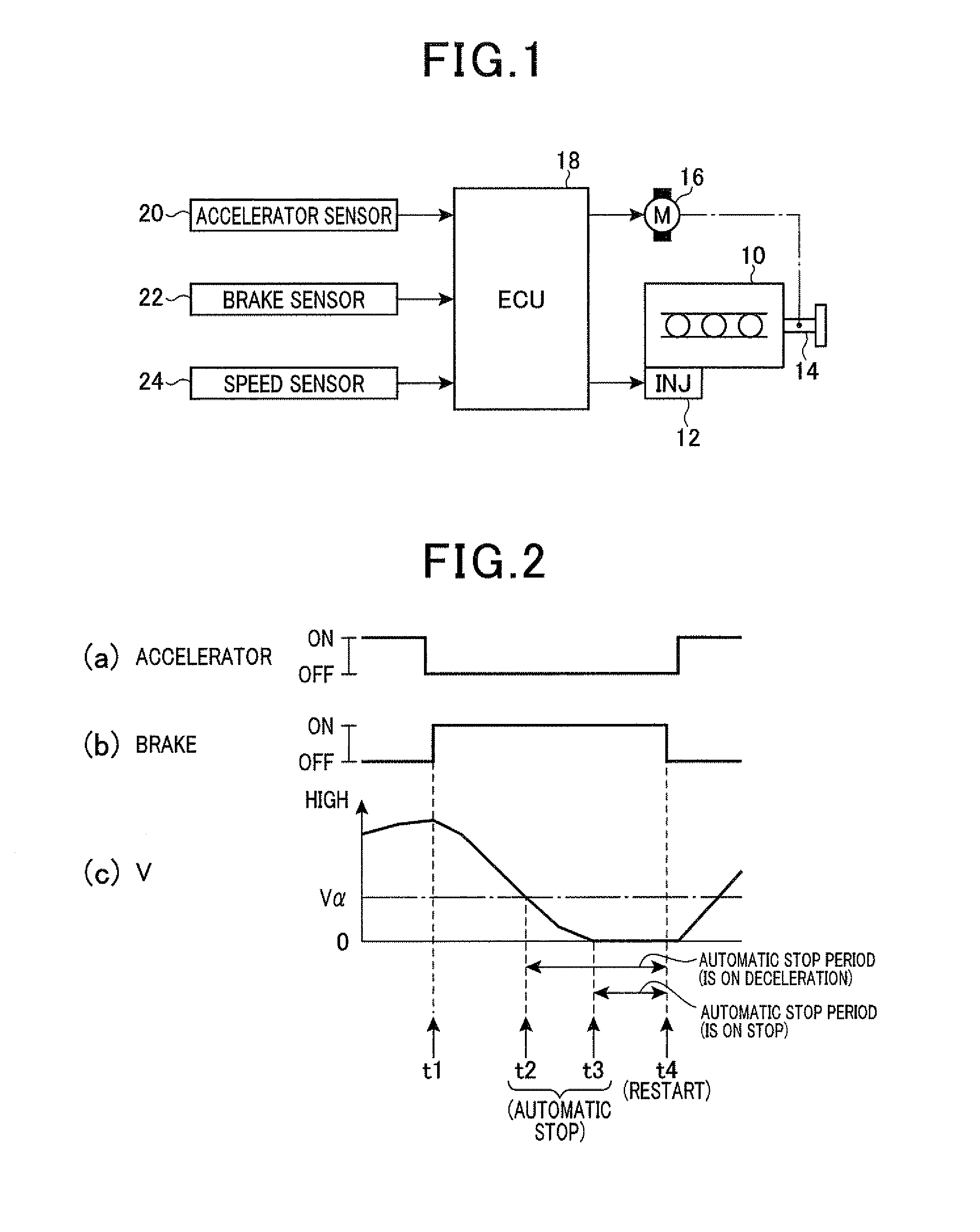
[0082]FIG. 1 shows a configuration of the on-vehicle engine system according to the present embodiment.
[0083]As shown in FIG. 1, the system is provided with an engine 10 mounted on a vehicle. The engine 10 has a plurality of cylinders, each comprising an electronically controlled fuel injection valve 12 that supplies and injects fuel into a combustion chamber of the engine 10. Energy is generated by combustion of the fuel injected by the injection valve 12, and then is extracted as a rotational force of an output shaft (i.e., a crankshaft 14) of the engine 10.
[0084]The crankshaft 14 is coupled to a starter 16. An ignition switch (not shown) is turned on to start the starter 16, and then the starter 16 gives initial rotation to the crankshaft 14 to start the engi...
second embodiment
[0136]Hereinafter, referring to the accompanying drawings, a control apparatus according to a second exemplary embodiment of the present invention will be described. In particular, differences from the above first exemplary embodiment will be mainly described.
[0137]FIG. 14 shows a configuration of the on-vehicle engine system according to the present embodiment. In FIG. 14, the same elements as shown in FIG. 1 are conveniently provided with the same reference letters.
[0138]As shown in FIG. 14, the rotational force of the crankshaft 14 is transmitted to drive wheels (right and left rear wheels) 28 via a differential gear 26 and a drive shaft (not shown), etc.
[0139]In the vehicle, a steering wheel 32 is disposed so as to steer a steered wheels 30 (right and left front wheels that can be steered) 30. A turning angle θtire of the steered wheels 30 is determined by a steering amount of the steering wheel 32. Specifically, the more the steering amount becomes, the more the turning angle θ...
PUM
 Abstract
Description
Claims
Application Information
 - R&D
- Intellectual Property
- Life Sciences
- Materials
- Tech Scout
- Unparalleled Data Quality
- Higher Quality Content
- 60% Fewer Hallucinations
Browse by: Latest US Patents, China's latest patents, Technical Efficacy Thesaurus, Application Domain, Technology Topic, Popular Technical Reports.
© 2025 PatSnap. All rights reserved.Legal|Privacy policy|Modern Slavery Act Transparency Statement|Sitemap|About US| Contact US: help@patsnap.com


