Blade mounting

a technology for mounting blades and rotor blades, which is applied in the direction of wind energy generation, motors, engine fuctions, etc., can solve the problems of difficult and risky operation of rotor blades mounted to the hub, affecting the performance of rotor blades, and unable to generally only be lifted. , to achieve the effect of fast, safe and secure method of blade mounting operation

Inactive Publication Date: 2012-06-07
GE WIND ENERGY NORWAY
View PDF3 Cites 28 Cited by
  • Summary
  • Abstract
  • Description
  • Claims
  • Application Information

AI Technical Summary

Benefits of technology

[0009]It is one object of the present invention to overcome the drawbacks and disadvantages of the above described prior art. The so

Problems solved by technology

The lifting of the rotor hub with several rotor blades mounted to the hub, is a difficult and risky operation because of the high total weight of the rotor hub and the rotor blades together.
The lifting is weather dependent and can generally only be performed on calm days with no wind.
The geographic places chosen for wind power plants to be built on are preferably windy places and it can therefore be understood that the mounting normally will be very costly.
The in situ mounting of rotor blades on the rotor hub of a wind power plant is accompanied by at least two problems to deal with, namely lifting the rotor blade from the ground up to the rotor hub and, after having mounted the first rotor blade to the rotor hub, handling the considerable imbalance which has been introduced due to the one-sided load of the blade.
A disadvantage of mobile cranes is that

Method used


Image

  • Blade mounting
  • Blade mounting
  • Blade mounting

Examples


Embodiment Construction

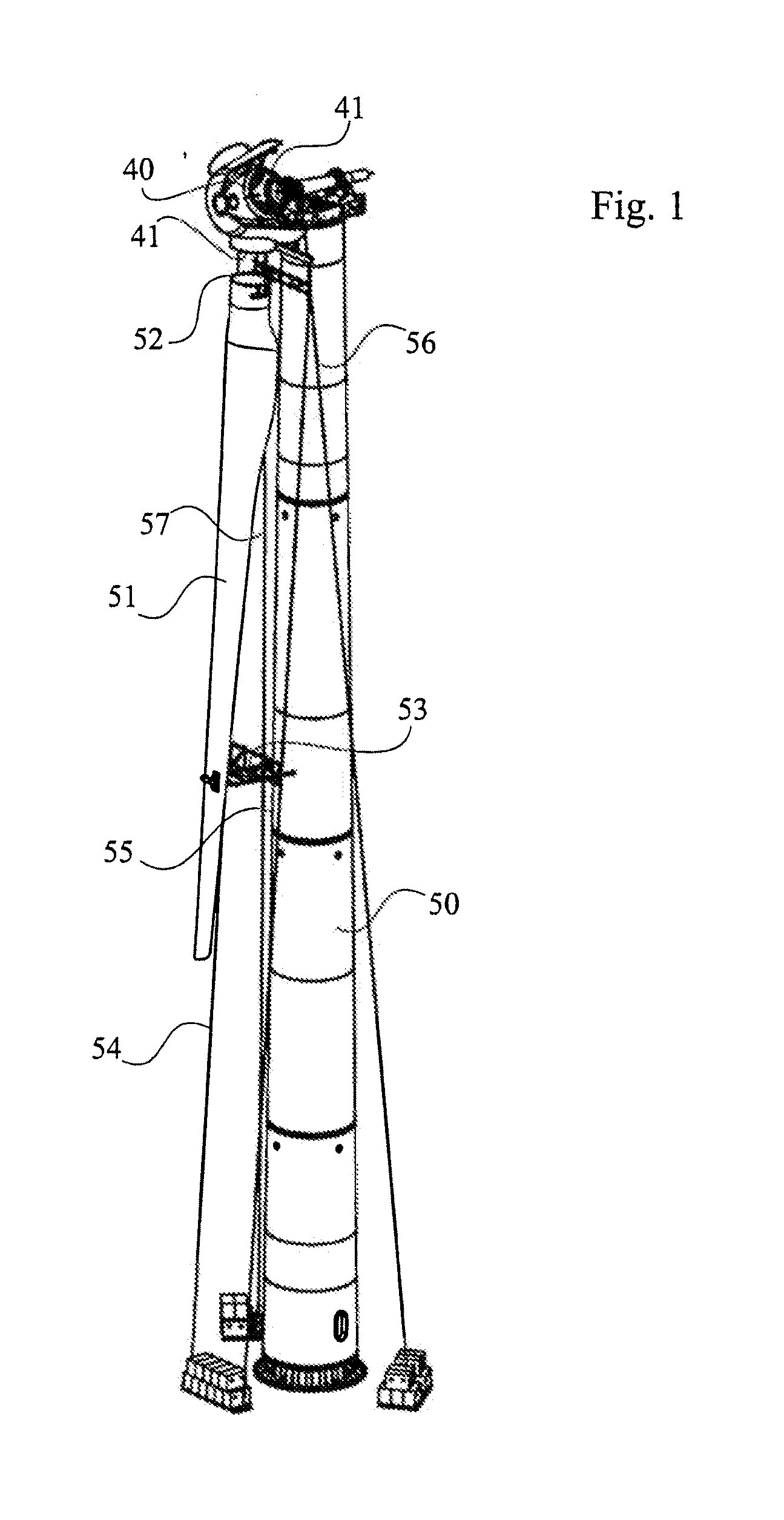
[0020]FIG. 1 is an overview of a wind power plant. A rotor blade 51 is being lifted up to the rotor hub 40 at the upper part of the tower 50 in order to be fitted with its rotor blade connection 52 to the flange 41 of the rotor hub 40, which is connected to the main shaft by means of a hub flange (shown in FIG. 2).

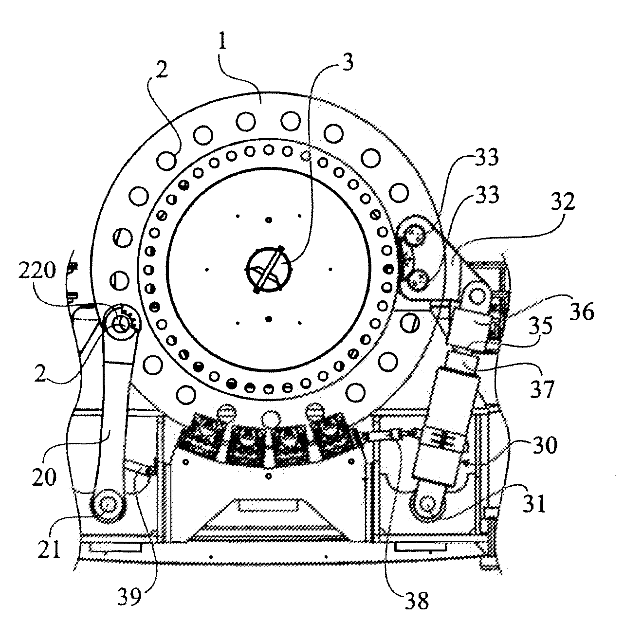
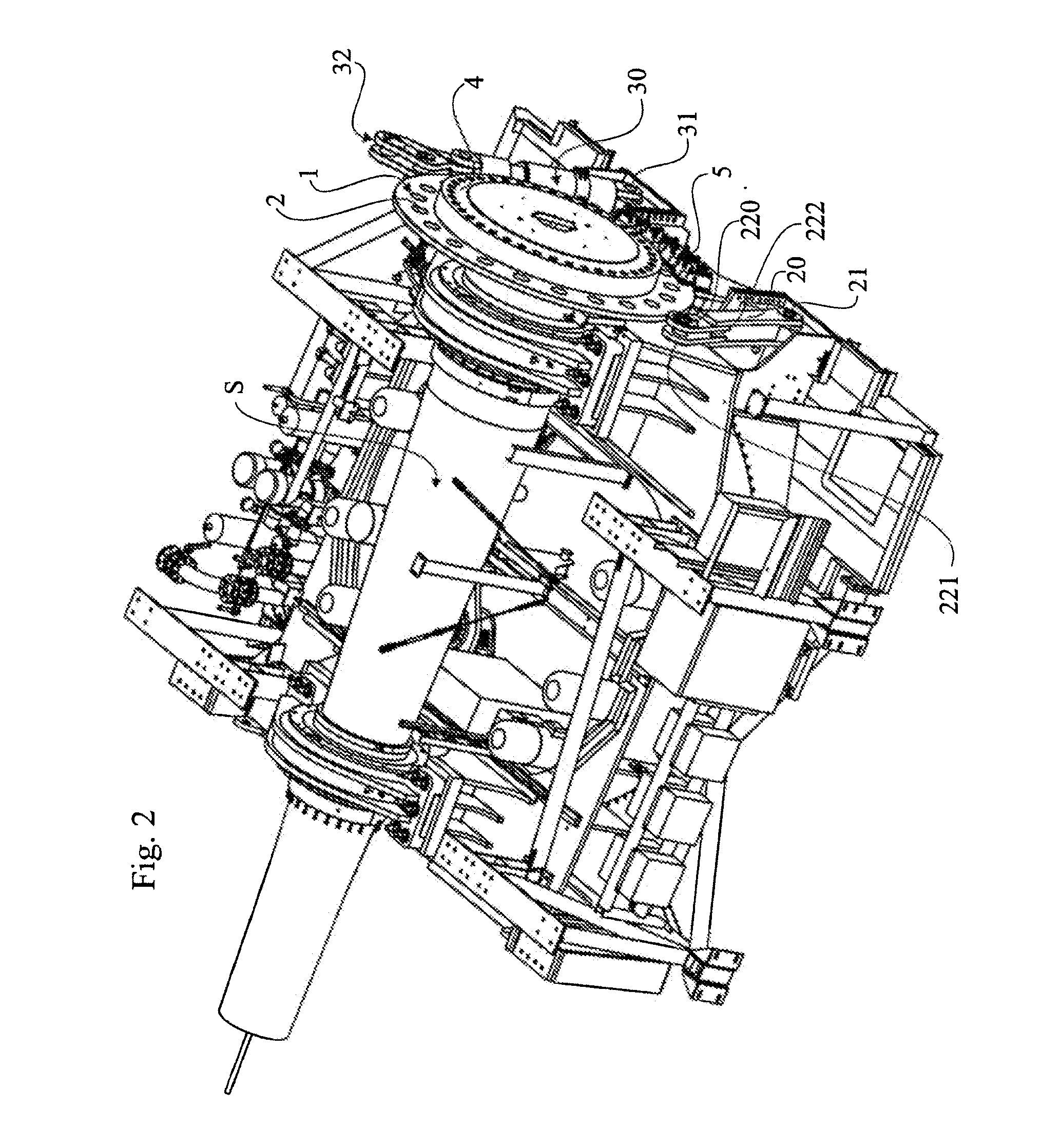
[0021]FIG. 2 is a side view of the interior of the machine housing of the wind power plant. A brake disc 1 is centrally mounted on the main shaft S of the wind turbine and has a large diameter, normally in the range of 1.5-3 meters. The brake disc 1 extends with a portion of its periphery into the gap of a number of brake units 5. The brake disc 1 is provided with a connecting means 2, consisting of a number of through bores evenly distributed on the brake disc 1 at a certain distance from the axis of the brake disc 1. The number of through holes and the degree of angles between the through holes may vary depending on the different needs. A locking device 20 is positioned ...


PUM

PropertyMeasurementUnit
Angleaaaaaaaaaa
Distanceaaaaaaaaaa

Abstract

The present invention concerns an arrangement for in situ mounting of rotor blades to a rotor hub of a wind power plant comprising rotor blades, a rotor hub (40), a disc (1), a means for rotation (30) of the disc (1) around its axis. The disc (1) is in connection with the rotor hub (40) in such a way that when the disc (1) rotates a certain degree of angle around its axis (3) it will cause the rotor hub (40) to rotate the same degree of angle around the axis of the rotor hub. When the means for rotation (30) comes into a desired position, the disc (1) is secured by a securing means (20; 36, 37).

Description

CROSS-REFERENCE TO RELATED APPLICATIONS[0001]This is a national stage application under 35 U.S.C. §371(c) of prior-filed, co-pending PCT patent application serial number PCT / EP2010 / 053133, filed on Mar. 11, 2010 which claims priority to U.S. provisional patent application Ser. No. 61 / 186,182, filed on Jun. 11, 2009 and Swedish patent application serial number 0950152-9, each of which is hereby incorporated by reference in its entirety.BACKGROUND OF THE INVENTION[0002]The field of the present invention concerns the area of construction of a wind power plant and more specifically an arrangement and a method for mounting rotor blades to a rotor hub of a wind power installation in situ. Various aspects of the invention also concern a wind power installation implementing the method.[0003]The most common way for mounting rotor blades to a rotor hub is to perform the mounting on the ground, i.e. all of the rotor blades are fitted to the flange of the rotor hub, which rotor hub is resting o...

Claims


Application Information

Patent Timeline
IPC IPC(8): B21K3/04
CPCF03D1/001F03D1/003F03D1/0658F03D7/0268F03D11/00Y10T29/37Y02E10/721Y02E10/722Y02E10/723Y02E10/728F05B2260/30F03D80/00F03D13/10F03D80/50Y02E10/72F05B2260/31F03D13/108F03D1/066
Inventor LINDBERG, MIKAELHEDBERG, JOHAN
Owner GE WIND ENERGY NORWAY
Why Eureka
Try Eureka