Optical fiber installation at customer premises

a technology for installing optical fiber and customer premises, applied in the direction of optical elements, instruments, chemistry apparatuses and processes, etc., can solve the problems of reducing installation time, affecting the safety of customers, and requiring relatively low cost, so as to achieve the effect of quickly and safely installing at customers' premises

Active Publication Date: 2012-06-07
OFS FITEL LLC
View PDF8 Cites 8 Cited by
  • Summary
  • Abstract
  • Description
  • Claims
  • Application Information

AI Technical Summary

Benefits of technology

[0012]The invention therefore enables an optical fiber or cable to be installed at a customer's premises quickly and safely without fasteners that might damage the fiber and / or adjacent surfaces, and in such a way that the completed installation will be virtually unnoticeable to persons inside the premises.

Problems solved by technology

While the use of conventional cable staples to route an optical fiber or cable along an existing wall, molding or other exposed surface may reduce installation time and incur relatively low cost, stapled installations have been rejected by many customers who opt for special molding or conduit solutions instead.
Staples can also physically damage walls and moldings, or impair or break an optical fiber if the staples are not carefully impacted or otherwise set in place over the length of the fiber.
Moreover, many customers prefer to have all service cables totally concealed inside their premises, which requires expensive hardware and significant installation time.

Method used


Image

  • Optical fiber installation at customer premises
  • Optical fiber installation at customer premises
  • Optical fiber installation at customer premises

Examples


Embodiment Construction

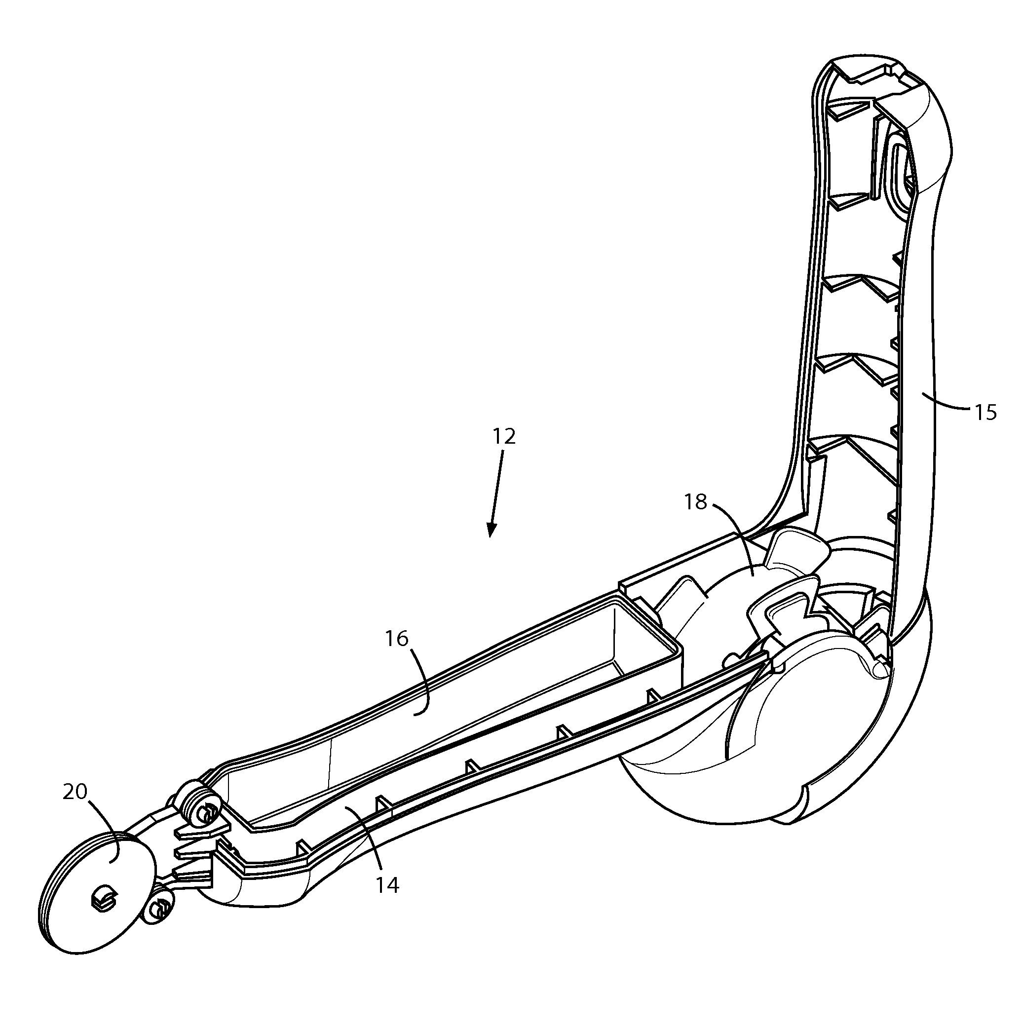
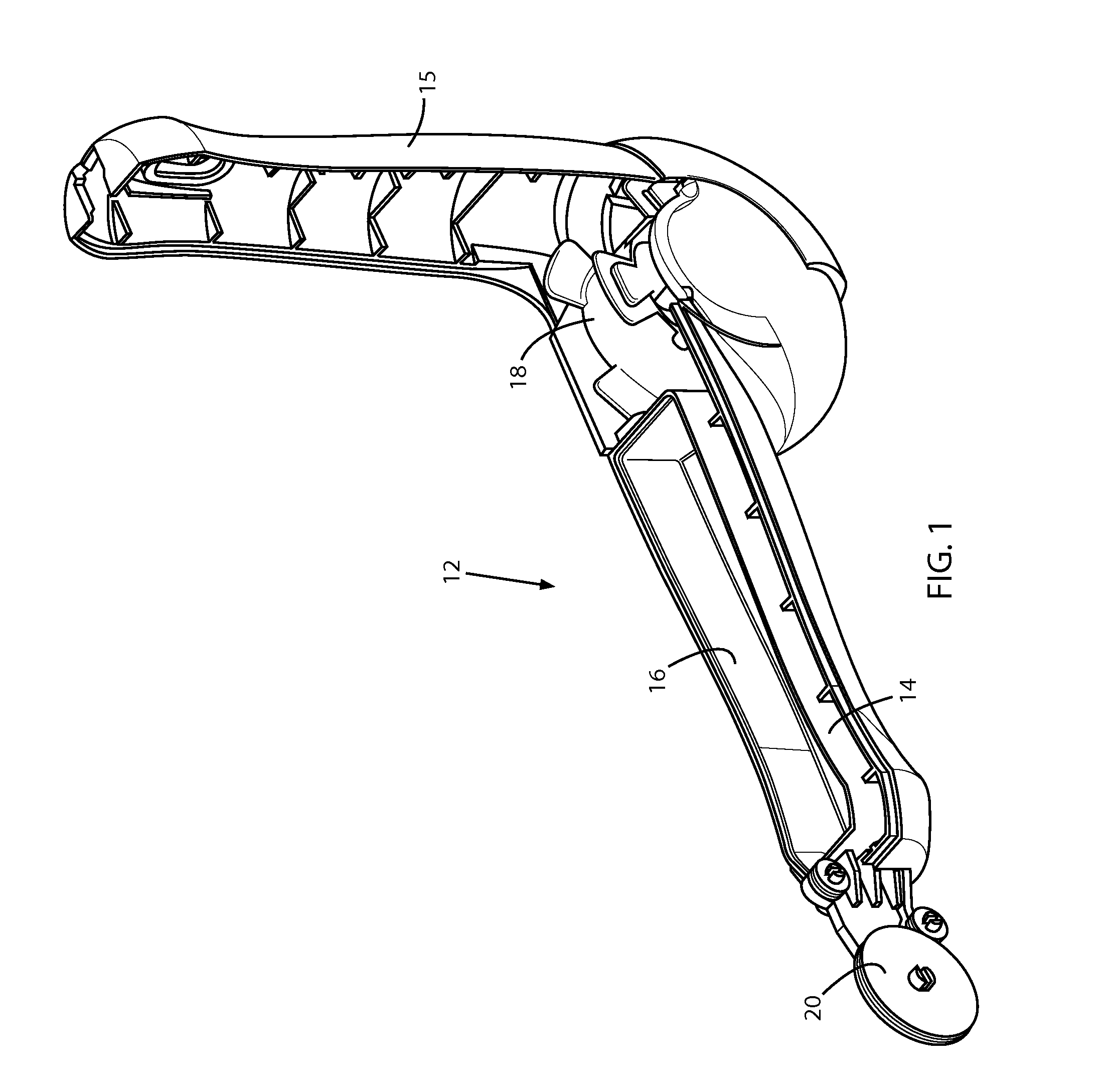
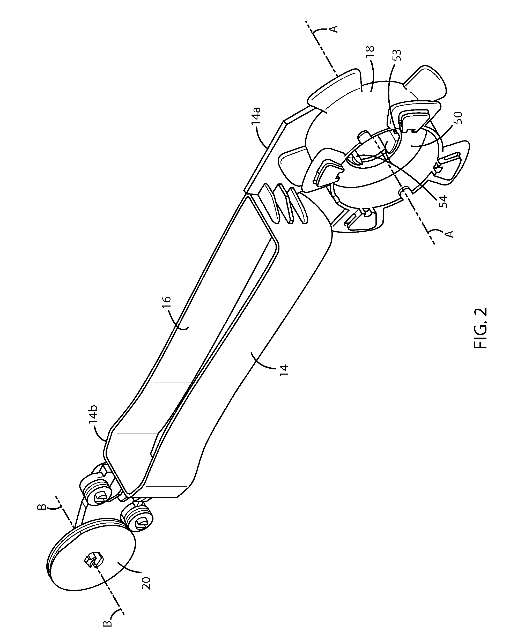
[0031]As used herein, the words “user” and “customer” are used inter-changeably to refer to one or more persons or legal entities that use telecommunication services offered by a service provider to acquire, e.g., Internet access, telephony, television and other information or data streams, wherein the services require the installation of one or more lengths of an optical fiber or cable at the location where the services are used by the person or entity (e.g., a home residence, apartment, or office building). Further, the words “residence” and “premises” are used interchangeably herein to connote the residence, office, or other structural living unit where the services are used by the person or entity.

[0032]The system disclosed herein allows an optical fiber or cable to be installed quickly and safely at a customer's residence, leaving few if any visible signs of the installation when completed. Co-pending U.S. patent application Ser. No. 12 / 986,990 filed Jan. 7, 2011, which is assi...


PUM

PropertyMeasurementUnit
lengthaaaaaaaaaa
bend radiusaaaaaaaaaa
axial lengthaaaaaaaaaa

Abstract

An optical fiber is permanently routed easily, quickly, and unobtrusively at a customer premises using an inventive hand tool, without staples or other fasteners. The fiber has an adhesive outer coating that is activated as the fiber is applied by the tool on an exposed surface such as a wall, ceiling, molding, groove, or corner at the premises. When the activated coating hardens, the fiber is bonded to the surface on which it was applied, and the hardened coating also provides physical protection for the fiber. In the disclosed embodiment, the coated fiber is supplied on a spool that mounts on the tool, and the coating is activated by guiding the fiber as it unwinds from the spool through a chamber containing an activating substance. The fiber with the activated coating is then guided to an applicator wheel on the tool which applies the fiber to the surface.

Description

CROSS REFERENCE TO RELATED APPLICATIONS[0001]The present application claims priority under 35 U.S.C. Sec. 119(e) of U.S. Provisional Patent Applications No. 61 / 365,963 filed Jul. 20, 2010, titled “Home Fiber Routing System”; No. 61 / 365,970 filed Jul. 20, 2010, titled “Home Fiber Routing System”; No. 61 / 371,828 filed Aug. 9, 2010, titled “Home Fiber Routing System”; and No. 61 / 483,931 filed May 9, 2011, titled “EZ-Bend ILU Micro-Drop Solution”, all of which are incorporated by reference in their entireties.BACKGROUND OF THE INVENTION[0002]1. Field of the Invention[0003]This invention concerns methods and systems for routing an optical fiber or cable inside the premises of a customer of a telecommunications services provider.[0004]2. Discussion of the Known Art[0005]U.S. Pat. No. 7,266,283 (Sep. 4, 2007) describes fiber optic storing and dispensing apparatus, including a casing containing a rotatable spool on which relatively long and short lengths of a fiber optic jumper cable are co...

Claims


Application Information

Patent Timeline
Patent Type & Authority Applications(United States)
IPC IPC(8): B32B37/12B32B37/14
CPCG02B6/4441G02B6/4453Y10T156/18G02B6/4463G02B6/4457G02B6/50
Inventor BUREK, DENIS E.DICKINSON, PAUL R.GEORGE, JOHNHENDRICKSON, DANIELWHITE, WILLARD C.BRADLEY, JOSEPH E.MALOFSKY, ADAM GREGGMALOFSKY, BERNARD MILESMANN, WILLIAM H.
Owner OFS FITEL LLC
Why Eureka
Try Eureka