
Power supply circuit with adaptive input selection and method for power supply

Inactive Publication Date: 2012-06-07
RICHTEK TECH
View PDF4 Cites 91 Cited by
  • Summary
  • Abstract
  • Description
  • Claims
  • Application Information

AI Technical Summary

Benefits of technology

[0016]In the foregoing power supply circuit, when the output voltage is generated by the first buck switching regulator, the charge pump may be disabled to reduce power consumption.

Problems solved by technology

In addition, because the wiring in a PCB is becoming narrower, the power consumption of the equivalent resistance Rpcb becomes significant.

Method used


Image

  • Power supply circuit with adaptive input selection and method for power supply
  • Power supply circuit with adaptive input selection and method for power supply
  • Power supply circuit with adaptive input selection and method for power supply

Examples


first embodiment

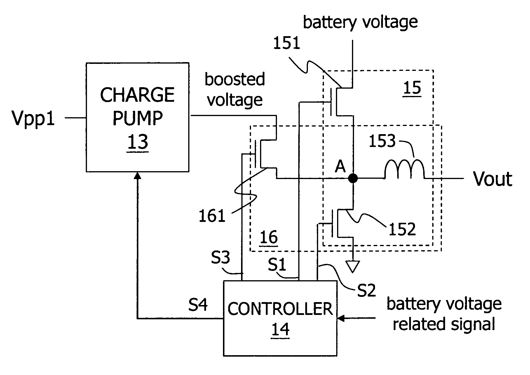
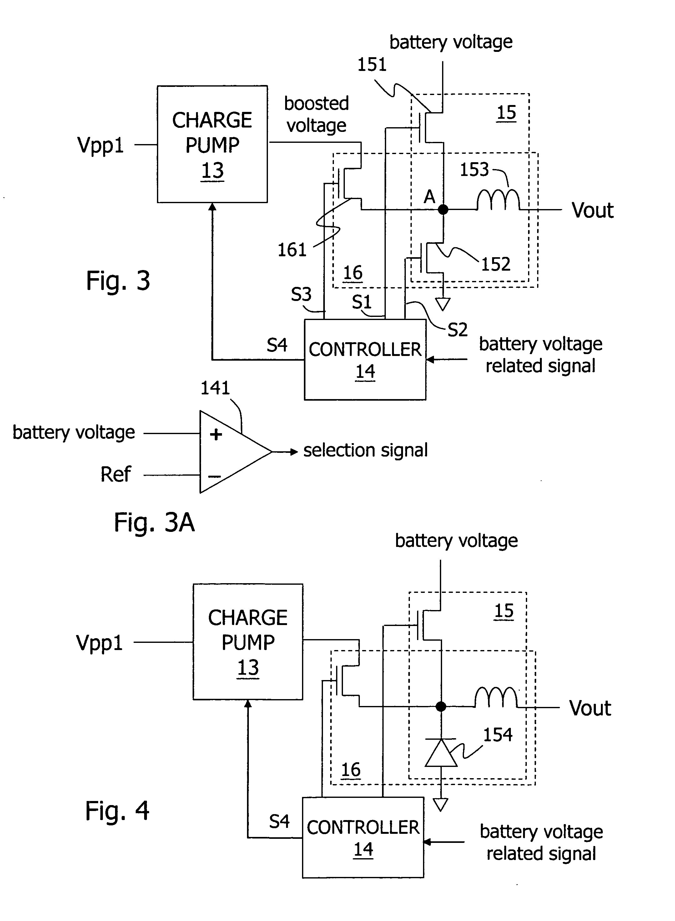
[0032]Please refer to FIG. 3 for a first embodiment according to the present invention, which operates as follows: when the battery voltage is higher than a threshold voltage which is high enough to generate an output Vout by buck conversion, the circuit converts the battery voltage to the output voltage Vout through a first buck switching regulator 15. This provides much better power conversion efficiency than the prior art because: first, the buck switching regulator provides better power conversion efficiency than a boost switching regulator; second, the power conversion is performed through only one buck switching regulator instead of being performed through two switching regulators; third, the current goes through a shorter path in a PCB. On the other hand, when the battery voltage decreases to become not higher than the threshold voltage, a charge pump 13 generates a boosted voltage, and a second buck switching regulator 16 converts the boosted voltage to the output voltage Vo...

third embodiment

[0037]FIG. 5 shows a third embodiment according to the present invention, wherein the charge pump 13 can be a charge pump which generates the boosted voltage by adding multiple voltages, or generates the boosted voltage as a fixed or variable multiple of one voltage. As shown in the figure, the charge pump 13 receives multiple input voltages Vpp1˜Vppn. In one embodiment, the charge pump 13 selects two input voltages from the multiple input voltages Vpp1˜Vppn according to the control signal S4, and adds the selected two input voltages to generate a proper boosted voltage higher than the output voltage Vout. In another embodiment, the charge pump 13 selects one input voltage from the multiple input voltages Vpp1˜Vppn according to the control signal S4, and generates the boosted voltage equal to a multiple of the selected input voltage, wherein the multiple of the selected input is not limited to an integer.

[0038]In addition, as shown in FIG. 5A, at least one of multiple input voltages...

fifth embodiment

[0040]FIG. 7 shows a fifth embodiment according to the present invention, in which one practical embodiment of the charge pump 13 is illustrated. As described above, the charge pump 13 can be embodied in many ways, so FIG. 7 is only one among many possible embodiments and should not be taken as a limitation to the present invention. As shown in the figure, when the battery voltage is higher than the threshold voltage, the battery voltage related signal causes the controller 14 to generate a set of signals S1 and S2 for operating the first power transistor 151 and the lower gate transistor 152 to convert the battery voltage to the output voltage Vout. When the battery voltage is not higher than the threshold voltage, the controller 14 generates the charge pump control signal S4 to enable the charge pump 13 to generate the boosted voltage, and the controller 14 also generates another set of signals S3 and S2 for operating the second power transistor 161 and the lower gate transistor 1...


PUM


Abstract

The present invention discloses a power supply circuit with adaptive input selection and a method for power supply. The power supply circuit includes: a charge pump for receiving at least one voltage and generating a boosted voltage; a first buck switching regulator coupled to a battery, for operating at least one first power transistor to convert a battery voltage to an output voltage according to a first control signal; a second buck switching regulator coupled to the charge pump, for operating at least one second power transistor to convert the boosted voltage to the output voltage according to a second control signal; and a controller generating the first control signal or the second control signal according to a level of the voltage of the battery, to select the first buck switching regulator or the second switching regulator for generating the output voltage.

Description

CROSS REFERENCE[0001]The present invention claims priority to TW099141881, filed on Dec. 2, 2010.BACKGROUND OF THE INVENTION[0002]1. Field of Invention[0003]The present invention relates to a power supply circuit with adaptive input selection, in particular to a power supply circuit that can adaptively selects its input according to a battery voltage. The present invention also relates to a power supply method with adaptive input selection.[0004]2. Description of Related Art[0005]FIG. 1 shows a schematic diagram of a prior art power supply circuit which generates an output voltage Vout from a battery and supplies the output voltage to a load, wherein the load is, for example, a display panel of a portable electronic device. As shown in the figure, the power supply circuit essentially includes two converters: a buck switching regulator 11 and a boost switching regulator 12. The buck switching regulator 11 receives a battery voltage and switches at least one power transistor therein t...

Claims


Application Information

Patent Timeline
IPC IPC(8): G05F1/10
CPCH02M3/158H02M3/07H02M2001/0022H02M1/0022H02M3/155
Inventor TSAI, KUO-CHENWEI, WEI-HSIN
Owner RICHTEK TECH
Features
  • Generate Ideas
  • Intellectual Property
  • Life Sciences
  • Materials
  • Tech Scout
  • Unparalleled Data Quality
  • Higher Quality Content
  • 60% Fewer Hallucinations
Learn More