Liquid crystal display apparatus

a technology of liquid crystal display and display screen, which is applied in the direction of instruments, optical light guides, optics, etc., can solve the problems of low workability, excessive materials, and a large weight, and achieve the effect of reducing the substrate area, improving workability and productivity

Inactive Publication Date: 2012-06-07
HITACHI CONSUMER ELECTRONICS CORP
View PDF4 Cites 4 Cited by
  • Summary
  • Abstract
  • Description
  • Claims
  • Application Information

AI Technical Summary

Benefits of technology

[0019]According to the present invention, the light guide plate used for the backlight unit is as large as one of four equal parts of the liquid crystal panel divided in the vertical and horizontal directions, the LED PWBs having the LEDs are disposed in three rows on the light guide plate, and the LEDs are arranged on each of the LED PWBs, thereby reducing a substrate area. Moreover, the four separate light guide plates improve workability and productivity.

Problems solved by technology

In this manufacturing method, unfortunately, the insertion of the reflective sheet 40 between the light guide plate 50 and the LED PWB 30 leads to low workability and the LED PWB needs to be large in size, resulting in excessive materials and a larger weight.

Method used


Image

  • Liquid crystal display apparatus
  • Liquid crystal display apparatus
  • Liquid crystal display apparatus

Examples


Embodiment Construction

[0043]An embodiment of the present invention will be specifically described below with reference to the accompanying drawings.

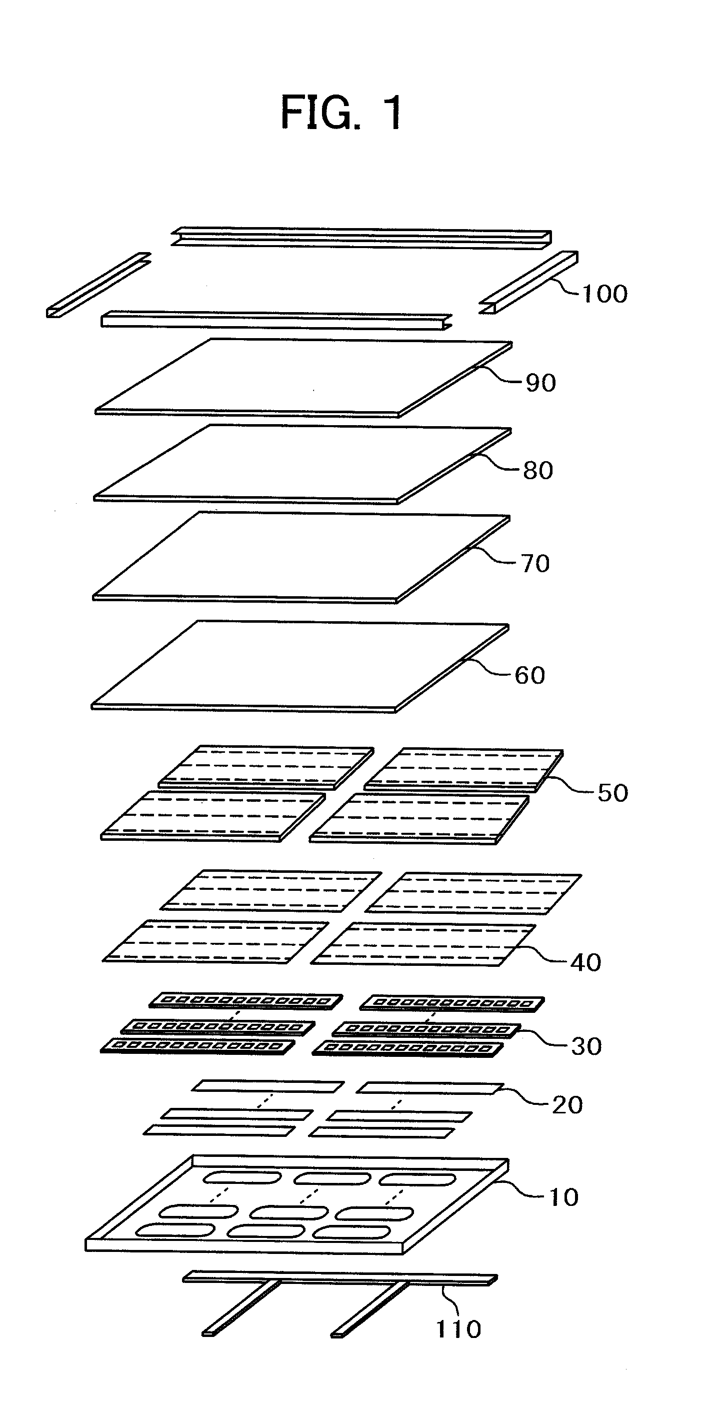
[0044]FIG. 1 is an exploded perspective view illustrating the configuration of the backlight unit of a liquid crystal display apparatus.

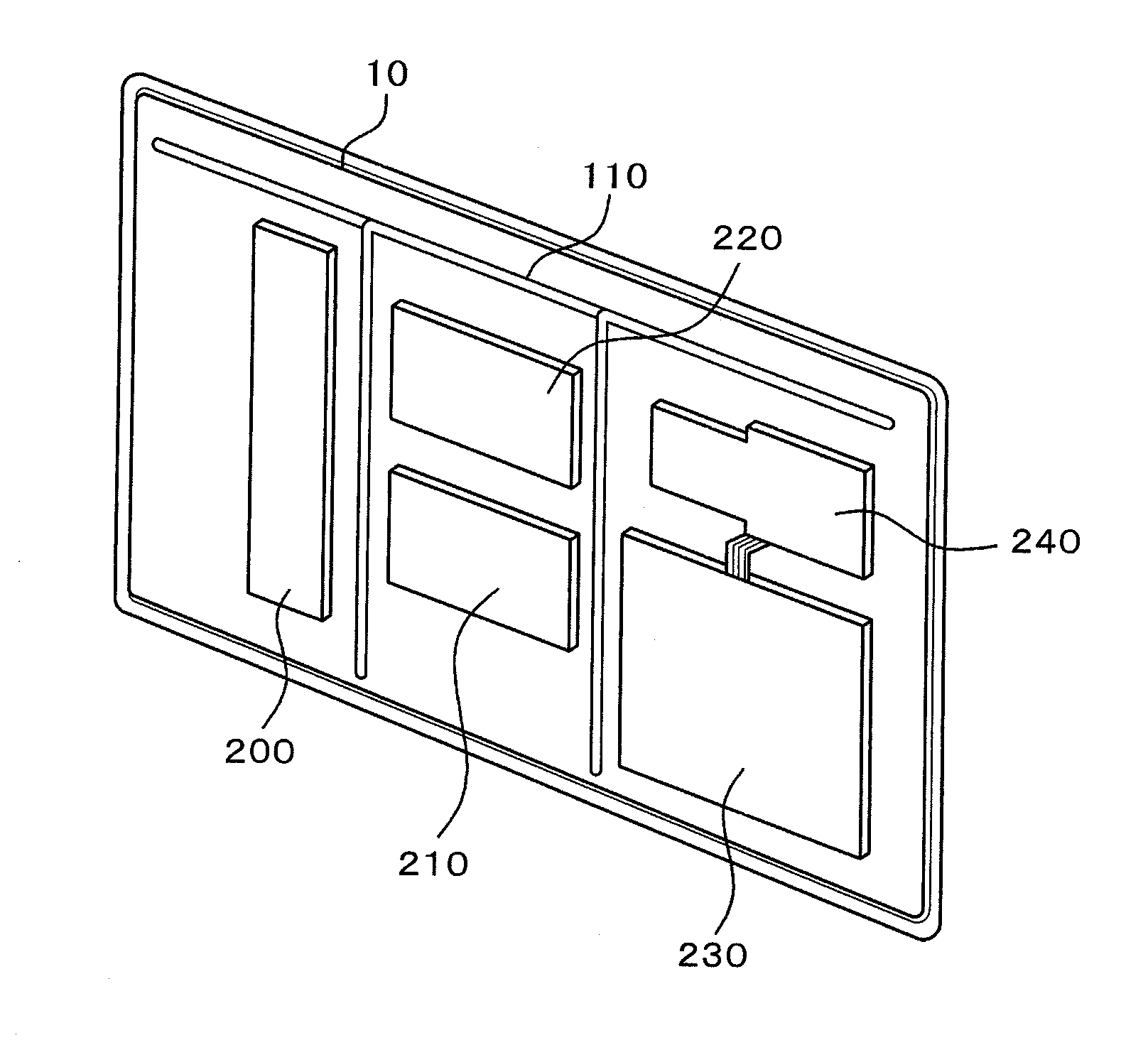
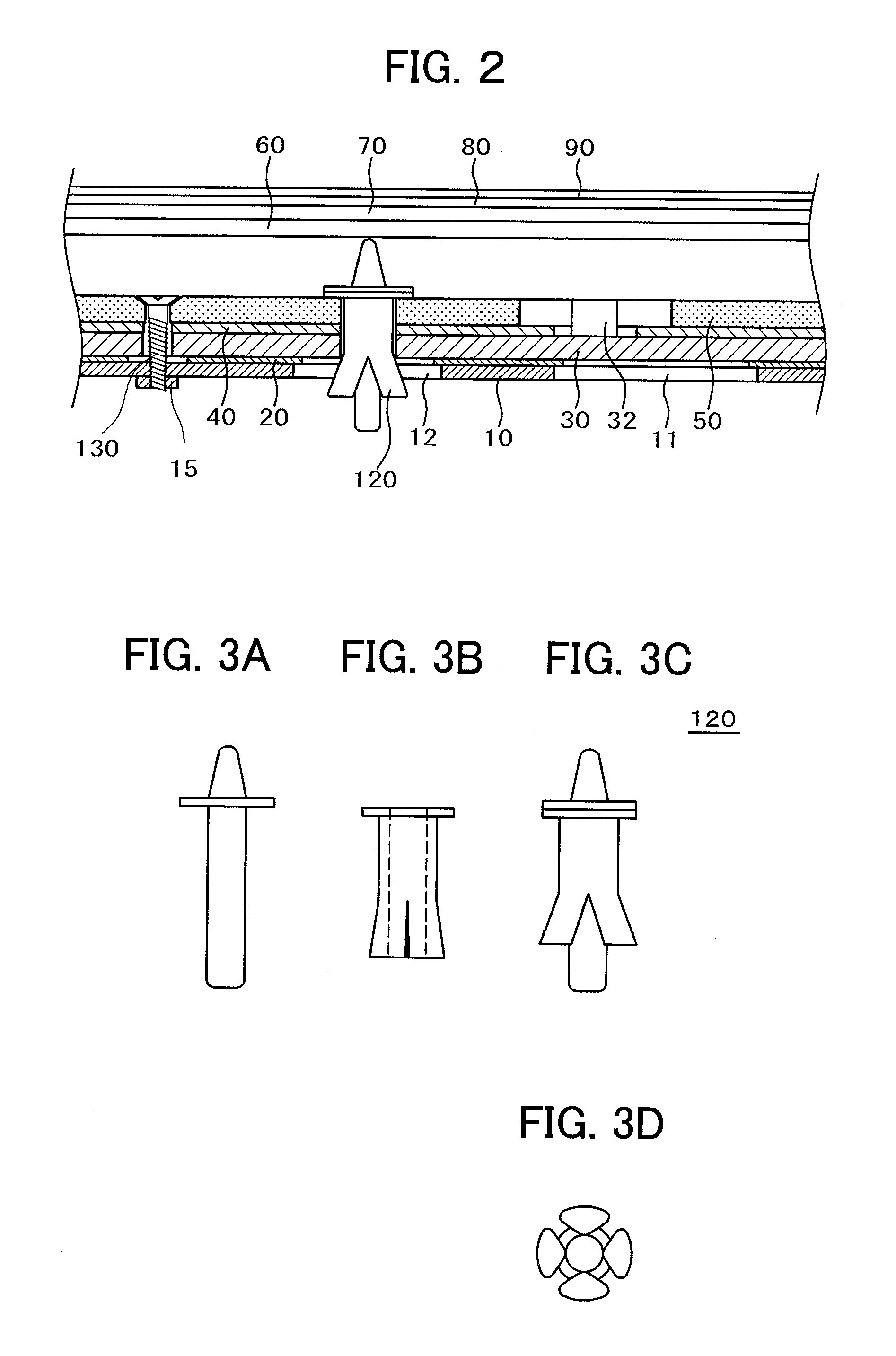
[0045]In FIG. 1, the backlight unit includes a chassis 10, insulating sheets 20 that insulate the chassis and LED PWBs, LED PWBs 30 having mounted LEDs, reflective sheets 40 that reflect LED light, light guide plates 50 that surface-emit LED light, a diffuser plate 60, a diffuser sheet 70, a prism sheet 80, and a polarized reflective sheet 90. These components are integrally fixed by a mold frame 100. The backlight unit illuminates a liquid crystal panel. The liquid crystal panel acting as a display screen contains liquid crystal materials that are sandwiched between two transparent substrates inside polarization filters of about 0.2 mm. The outer edge of the liquid crystal panel is sealed with a sealing material to prevent l...


PUM

PropertyMeasurementUnit
widthaaaaaaaaaa
widthaaaaaaaaaa
thicknessaaaaaaaaaa

Abstract

A liquid crystal display apparatus includes a backlight unit in which a diffusing member and an adjusting member are disposed on exit surfaces of light guide plates near a liquid crystal panel. The diffusing member diffuses light from the exit surfaces and the adjusting member adjusts the distribution of light from the exit surfaces. The light guide plate is as large as one of four equal parts of the liquid crystal panel as divided in vertical and horizontal directions.

Description

CLAIM OF PRIORITY[0001]The present application claims priority from Japanese patent application serial No. 2010-270149, filed on Dec. 3, 2010, the content of which is hereby incorporated by reference into this application.BACKGROUND[0002]1. Technical Field[0003]The present invention relates to a liquid crystal display apparatus including a backlight unit in which LEDs are used for illumination of the liquid crystal display apparatus.[0004]2. Description of the Related Art[0005]Conventionally, fluorescent tubes such as Cold Cathode Fluorescent Lamps(CCFLs) and External Electrode Fluorescent Lamps (EEFLs) have been used as the light sources of backlight units. Backlight units are light source supply units for illuminating liquid crystal display apparatuses.[0006]In recent years, Light-Emitting Diodes (LEDs) have been mainly used as the light sources of the backlight units of liquid crystal display apparatuses. LEDs having longer lives than conventional fluorescent lamps with simple st...

Claims


Application Information

Patent Timeline
Patent Type & Authority Applications(United States)
IPC IPC(8): G02F1/13357
CPCG02B6/0055G02B6/0068G02B6/0073G02B6/0078G02F1/133611G02B6/0088G02B6/009G02F1/133524G02F1/133603G02B6/008
Inventor YAMASHITA, YOSHIHARUKAKU, NOBUYUKIAKAZAWA, YOSHIYUKIYAMAMOTO, MASAHIRO
Owner HITACHI CONSUMER ELECTRONICS CORP
Why Eureka
Try Eureka