Molded Ultra Thin Semiconductor Die Packages, Systems Using the Same, and Methods of Making the Same

a technology of ultra-thin semiconductor dies and die packages, which is applied in the direction of semiconductor devices, semiconductor/solid-state device details, electrical apparatus, etc., can solve the problems of increasing the design, size and assembly requirements of interconnect substrates, increasing substrate area and cost, and increasing the demand for a smaller form factor, so as to increase the functionality and features of electronic products, increase the substrate area and cost, and reduce the effect of product yield

Active Publication Date: 2010-03-04
SEMICON COMPONENTS IND LLC
View PDF43 Cites 6 Cited by
  • Summary
  • Abstract
  • Description
  • Claims
  • Application Information

AI Technical Summary

Benefits of technology

[0003]As part of making his invention, the inventor has recognized that there is a need to address these issues and that it would be advantageous to find ways to enable increases in functionality and features of electronic products without causing increases in substrate areas and costs, and decreases in product yields. As also part of making his invention, the inventor has recognized that many electronic products have several components, particularly semiconductor die, that can be grouped together in several small groups that provide specific functions. As also part of making his invention, the inventor has discovered that the substrate area required for a circuit group can be significantly decreased by packaging semiconductor die and other components in molded ultra-thin packages that can be stacked on top of one another to reduce board space and increase functionality, where each such package may be as thin as the semiconductor die it houses.

Problems solved by technology

This, in turn, has placed ever increasing demands on the design, size, and assembly of the interconnect substrates.
As the number of assembled components increases, substrate areas and costs increase, while demand for a smaller form factor increases.

Method used


Image

  • Molded Ultra Thin Semiconductor Die Packages, Systems Using the Same, and Methods of Making the Same
  • Molded Ultra Thin Semiconductor Die Packages, Systems Using the Same, and Methods of Making the Same
  • Molded Ultra Thin Semiconductor Die Packages, Systems Using the Same, and Methods of Making the Same

Examples


Embodiment Construction

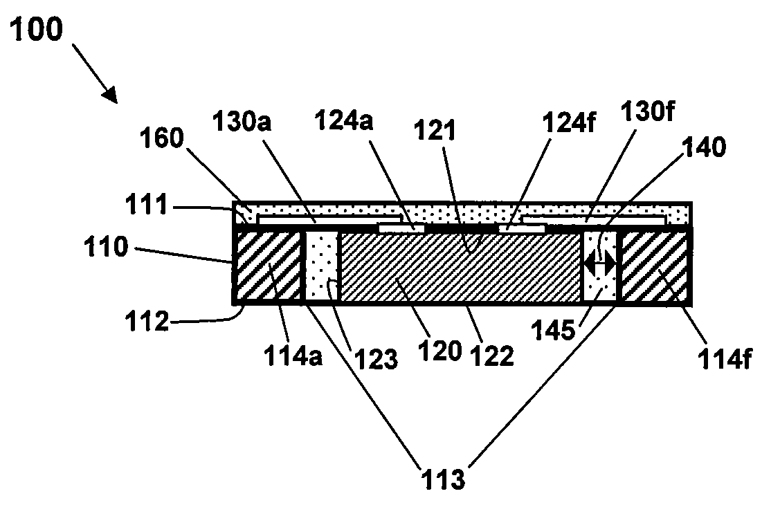
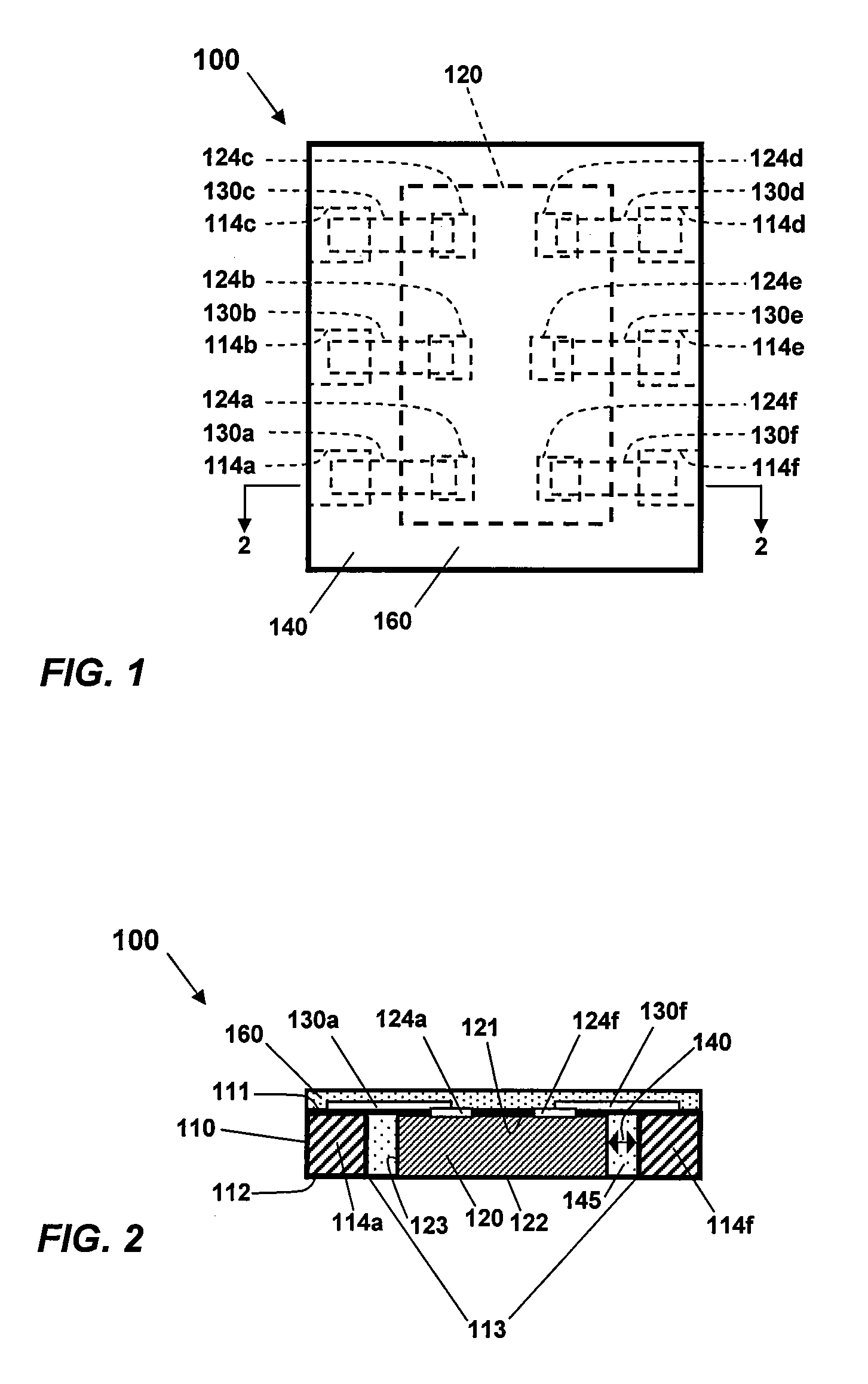
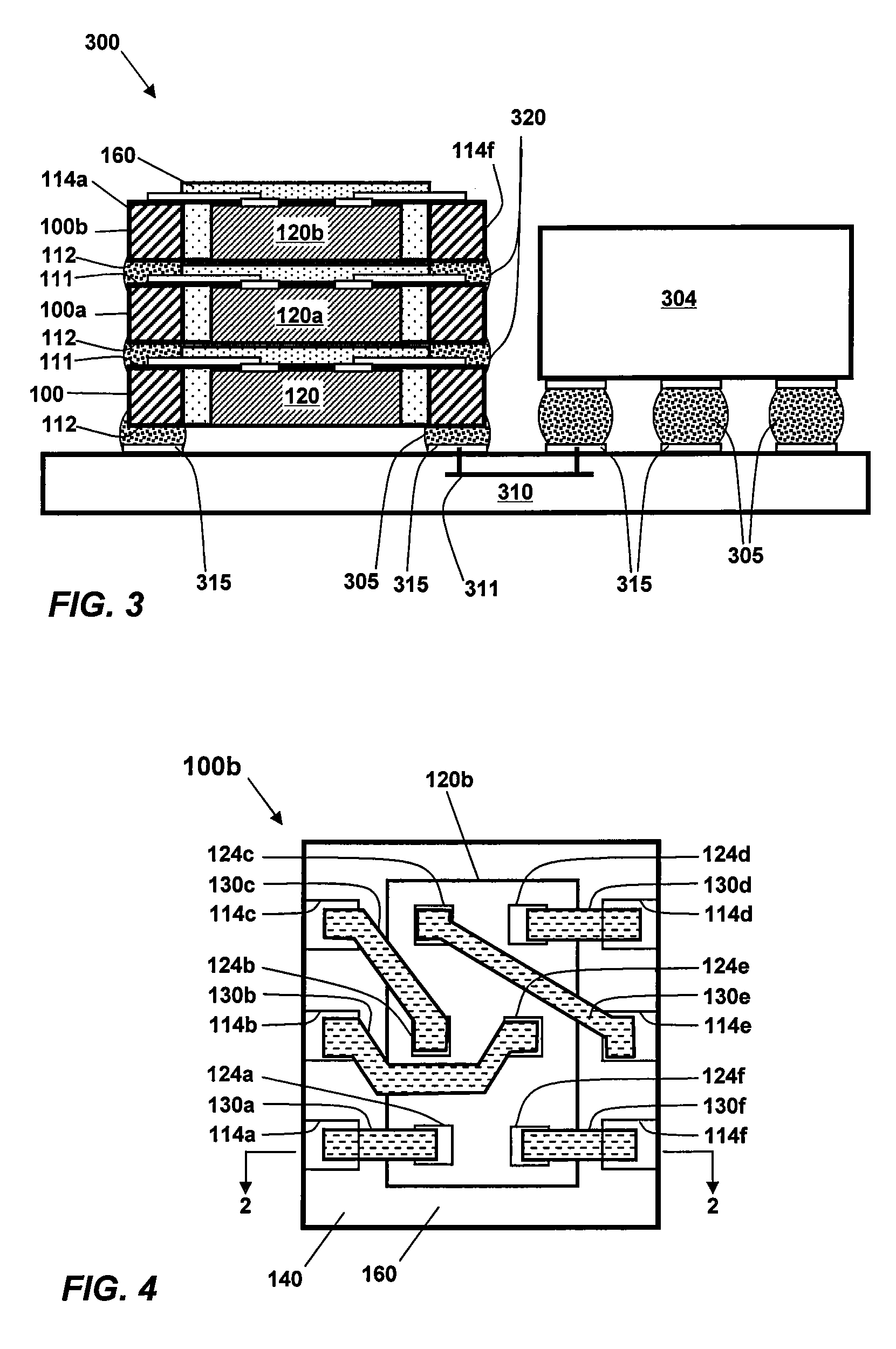
[0016]The present invention will be described more fully hereinafter with reference to the accompanying drawings, in which exemplary embodiments of the invention are shown. This invention may, however, be embodied in different forms and should not be construed as limited to the embodiments set forth herein. Rather, these embodiments are provided so that this disclosure is thorough and complete and fully conveys the scope of the invention to one skilled in the art. In the drawings, the thicknesses of layers and regions may be exaggerated for clarity. The same reference numerals are used to denote the same elements throughout the specification. The elements may have different interrelationships and different positions for different embodiments.

[0017]It will also be understood that when a layer is referred to as being “on” another layer or substrate, it can be directly on the other layer or substrate, or intervening layers may also be present. In the drawings, the thicknesses and sizes...


PUM


Abstract

Disclosed are molded ultra-thin semiconductor die packages, systems that incorporate such packages, and methods of making such packages. An exemplary package comprises a leadframe having an aperture formed between the leadframe's first and second surfaces, and a plurality of leads disposed adjacent to the aperture. The package further comprises a semiconductor disposed in the aperture of the leadframe with its top surface substantially flush with the leadframe's first surface, and at least one gap between at least one side surface of the semiconductor die and at least one lead of the leadframe. A body of electrically insulating material is disposed in the at least one gap. A plurality of conductive members interconnect leads of the leadframe with conductive regions on the die's top surface, with at least one conductive member having a portion disposed over at least a portion of the body of insulating material.

Description

CROSS-REFERENCES TO RELATED APPLICATIONS[0001]NOT APPLICABLE.BACKGROUND OF THE INVENTION[0002]Personal portable electronic products, such as cell phones, personal data assistants, digital cameras, laptops, etc., are generally comprised of several packaged semiconductor IC chips and surface mount components assembled onto interconnect substrates, such as printed circuit boards and flex substrates. There is an ever increasing demand to incorporate more functionality and features into personal portable electronic products, while at the same time shrink the sizes of such devices. This, in turn, has placed ever increasing demands on the design, size, and assembly of the interconnect substrates. As the number of assembled components increases, substrate areas and costs increase, while demand for a smaller form factor increases.BRIEF SUMMARY OF THE INVENTION[0003]As part of making his invention, the inventor has recognized that there is a need to address these issues and that it would be a...

Claims


Application Information

Patent Timeline
Patent Type & Authority Applications(United States)
IPC IPC(8): H01L23/495H01L21/60
CPCH01L21/563H01L2224/0401H01L23/3121H01L23/488H01L23/4952H01L23/49572H01L24/19H01L24/20H01L24/97H01L25/105H01L25/50H01L2224/04105H01L2224/16H01L2224/20H01L2924/01029H01L2924/01033H01L2924/01078H01L2924/01082H01L2924/13091H01L2924/14H01L2924/15173H01L2924/15192H01L2924/15331H01L2924/19105H01L2924/01006H01L2924/014H01L2225/1029H01L2225/1058H01L2924/18162H01L21/6835H01L2924/181H01L2924/00
Inventor LIU, YONG
Owner SEMICON COMPONENTS IND LLC
Why Eureka
Try Eureka