Adjustable light for underwater photography

a technology for underwater photography and adjustment light, which is applied in underwater equipment, lighting and heating apparatus, instruments, etc., can solve problems such as flooding and corrosion, introducing physical damage or dirt and grime to seals, and generating considerable heat, so as to reduce overall weight, reduce heat path, and reduce the effect of corrosion

Active Publication Date: 2012-06-07
LIGHT & MOTION INDS
View PDF10 Cites 18 Cited by
  • Summary
  • Abstract
  • Description
  • Claims
  • Application Information

AI Technical Summary

Benefits of technology

[0004]When an underwater photographer, including a video photographer, dives below about thirty feet during daylight, virtually all red has been filtered out of the ambient light. Because of the color adjustment (white balance) that is usually made by the diver's video camera, the colors in the video images will be adjusted to replace the red, but light projected from a diving light will compete with ambient light and areas of the video image that include the artificial light will appear overly red when color-balanced by the camera. The situation is different in night diving, in which the only light available is that from the diving light, and unbalance of color in different areas of the image is not a problem.
[0019]The light unit of the invention is charged using external wet style connectors, allowing the body unit to be sealed at the factory and never opened in the field, improving reliability for the diver.

Problems solved by technology

The tight LED array generates considerable heat, making the LED mounting board and surrounding areas hotter than would be the case if the LEDs were spread around the entire face of the housing.
Opening and closing a pressure seal repeatedly can and does introduce physical damage or dirt and grime to the seal, providing a path to potential flooding and corrosion.
Without proper heat dissipation the drive electronics can overheat and fail.

Method used


Image

  • Adjustable light for underwater photography
  • Adjustable light for underwater photography
  • Adjustable light for underwater photography

Examples


Embodiment Construction

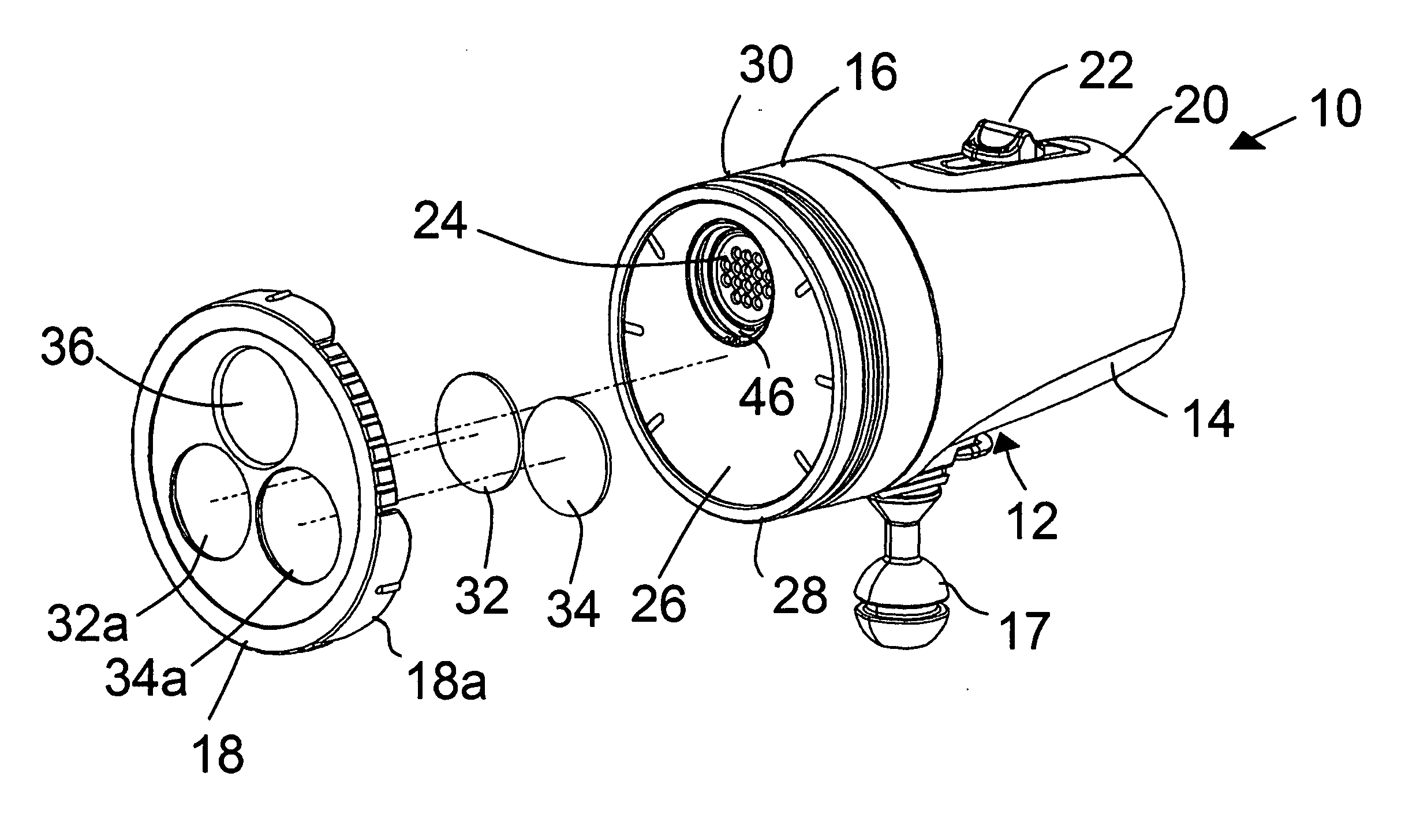
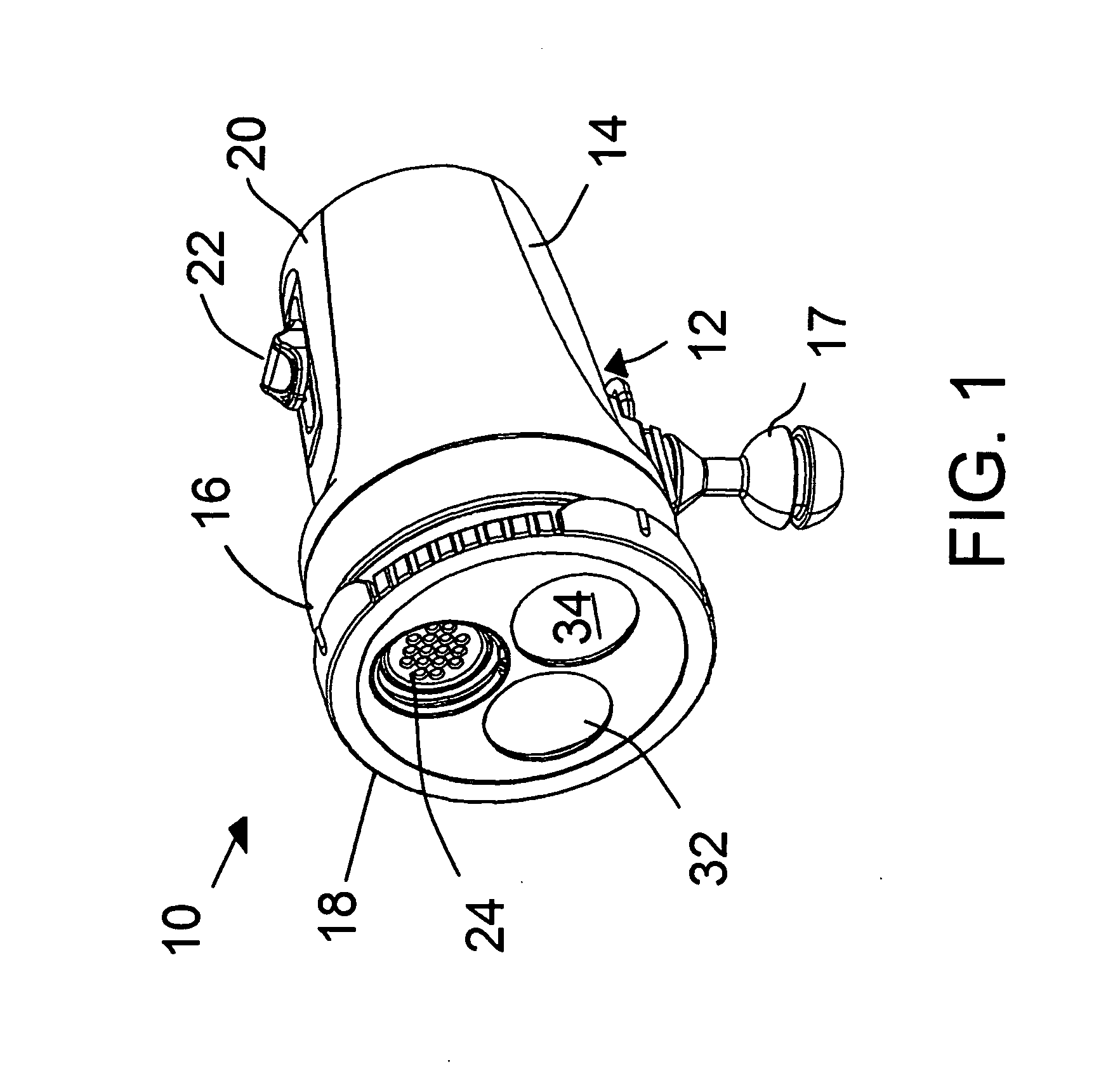
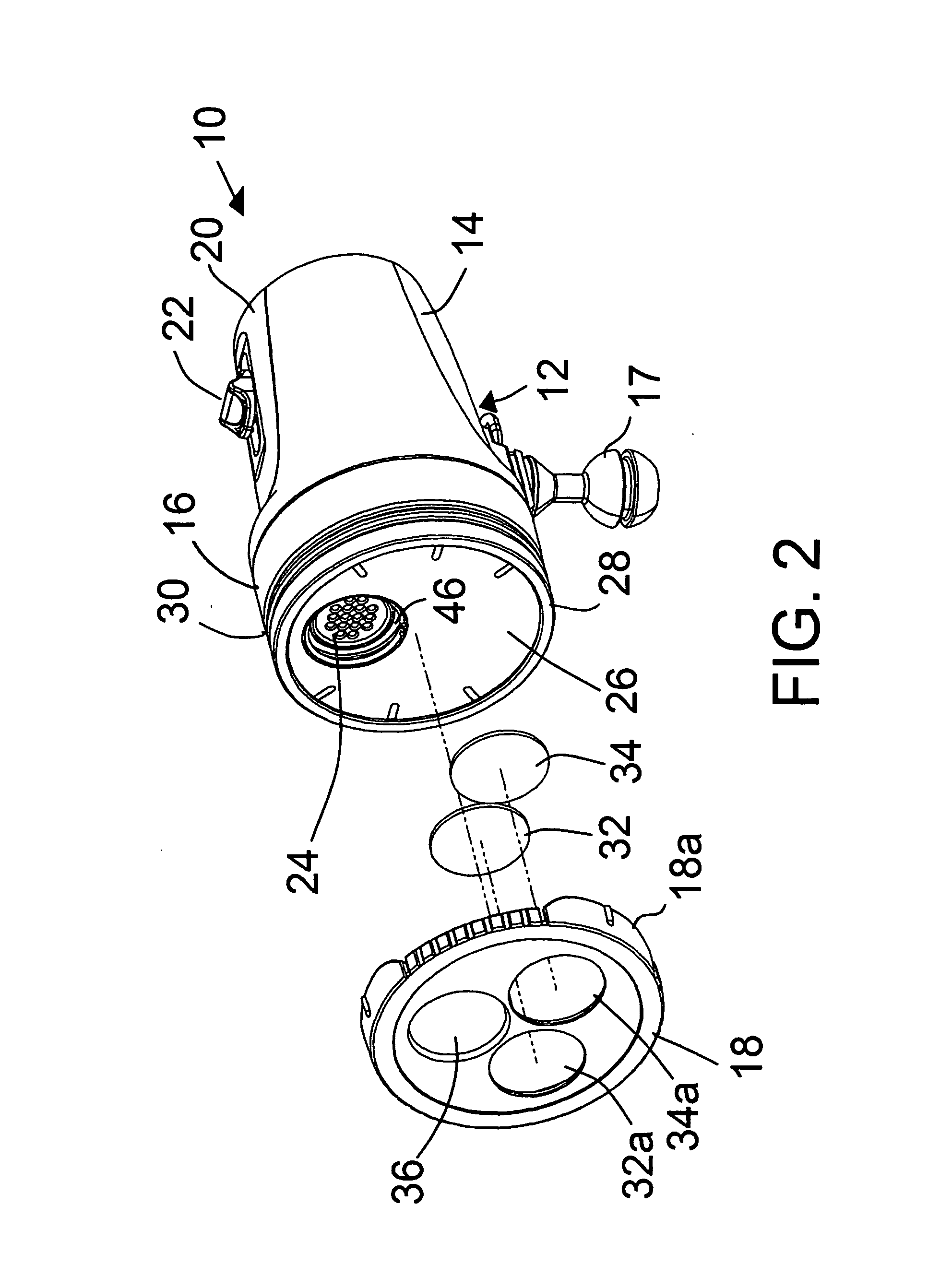
[0041]In the drawings, FIG. 1 shows a dive light 10 having a housing 12 formed of a casing 14, a front section or face assembly 16 attached to the casing, which can be by sealed threaded connection, a mounting interface device 17 and a rotatable filter ring 18. The device 17 is shown as a standard interface, to be received in a socket on a camera light arm accessory. On the casing is a switch assembly 20 with slide switch 22, for switching the dive light on and off and selecting a desired power level. At the front of the dive light device a beam is projected by an array 24 of LEDs in a tight cluster as shown. These may be sixteen in number.

[0042]With reference to both FIGS. 1 and 2, the filter ring 18 snaps onto and off a position of covering the front face 26 of the unit. The front of the unit has a bezel ring 28, forming an annular recess 30, which is gripped by overhanging structure (not shown in FIGS. 1 and 2) on the rim 18a of the filter ring to hold the filter ring in place on...


PUM


Abstract

An underwater diving light has a rotatable front filter ring for selecting light filtration as needed for underwater still or video photography conditions. The filter ring is removable and interchangeable with different rings. Another important feature is efficient cooling of the LEDs and other internal electronics of the diving light assembly. The water is in contact with a metallic front face that conducts heat directly away from a metal core circuit board carrying the LED array or arrays. In one form of the diving light water channels are provided so that the ambient water can enter the assembly to spaces behind the LCD circuit board to efficiently cool the LEDs and associated electronics. The front plate assembly can be removable, for rinsing the internal cooling cavities, for interchange with different front face assemblies, and for air travel when the LCDs must be removed from driving electronics for safety concerns.

Description

[0001]This application claims benefit of provisional application Ser. No. 61 / 414,873, filed Nov. 17, 2010.BACKGROUND AND SUMMARY OF THE INVENTION[0002]The invention concerns underwater video lighting, and particularly a unit producing a powerful beam from LED sources, with the ability to adjust light filtration by rotation of a front filter ring. The underwater light may produce flood light at about 4000 lumens and weighs less than two pounds.[0003]A number of underwater lighting devices are available for divers, some with rechargeable batteries and some also including flip-down color filters, such as red filters.[0004]When an underwater photographer, including a video photographer, dives below about thirty feet during daylight, virtually all red has been filtered out of the ambient light. Because of the color adjustment (white balance) that is usually made by the diver's video camera, the colors in the video images will be adjusted to replace the red, but light projected from a div...

Claims


Application Information

Patent Timeline
Patent Type & Authority Applications(United States)
IPC IPC(8): G03B15/02F21V9/40
CPCG03B15/02G03B2215/0567G03B2215/0592F21V29/004F21V31/005Y10S362/80F21V9/083F21Y2101/02F21Y2105/001F21V29/20B63C11/52F21L4/00F21Y2105/10F21Y2115/10F21V14/085F21V29/56F21V29/89
Inventor ARMER, JARODFOSS, DOUGOLSSON, MARKMCCASLIN, CHRISTOPHER
Owner LIGHT & MOTION INDS
Why Eureka
Try Eureka