Method and apparatus for turning a rotor blade bearing on wind turbines without using a mobile crane

a technology for wind turbines and bearings, applied in the direction of propellers, propulsive elements, water-acting propulsive elements, etc., can solve the problems of increasing wear and tear, increasing the abrasion of the respective locale, and affecting the safety of the rotor blade bearings. , to achieve the effect of increasing safety

Active Publication Date: 2012-06-07
VESTAS WIND SYST AS
View PDF2 Cites 24 Cited by
  • Summary
  • Abstract
  • Description
  • Claims
  • Application Information

AI Technical Summary

Benefits of technology

[0071]When the adapter has been attached, the top side typically abuts the slewing ring bearing and thus usually abuts the hub flange as well. The underside parallel thereto typically abuts the rotor blade flange. The offset arrangement of the through hole allows a difference between the bolt circle diameter of the hub flange and the bolt circle diameter of the rotor blade flange to be compensate

Problems solved by technology

In wind turbines with electric blade control, the toothing of the rotor blade bearing, i.e., the toothing of the slewing ring bearing in the range between about 0° and 5° blade pitch angle (blade positio

Method used


Image

  • Method and apparatus for turning a rotor blade bearing on wind turbines without using a mobile crane
  • Method and apparatus for turning a rotor blade bearing on wind turbines without using a mobile crane
  • Method and apparatus for turning a rotor blade bearing on wind turbines without using a mobile crane

Examples


Embodiment Construction

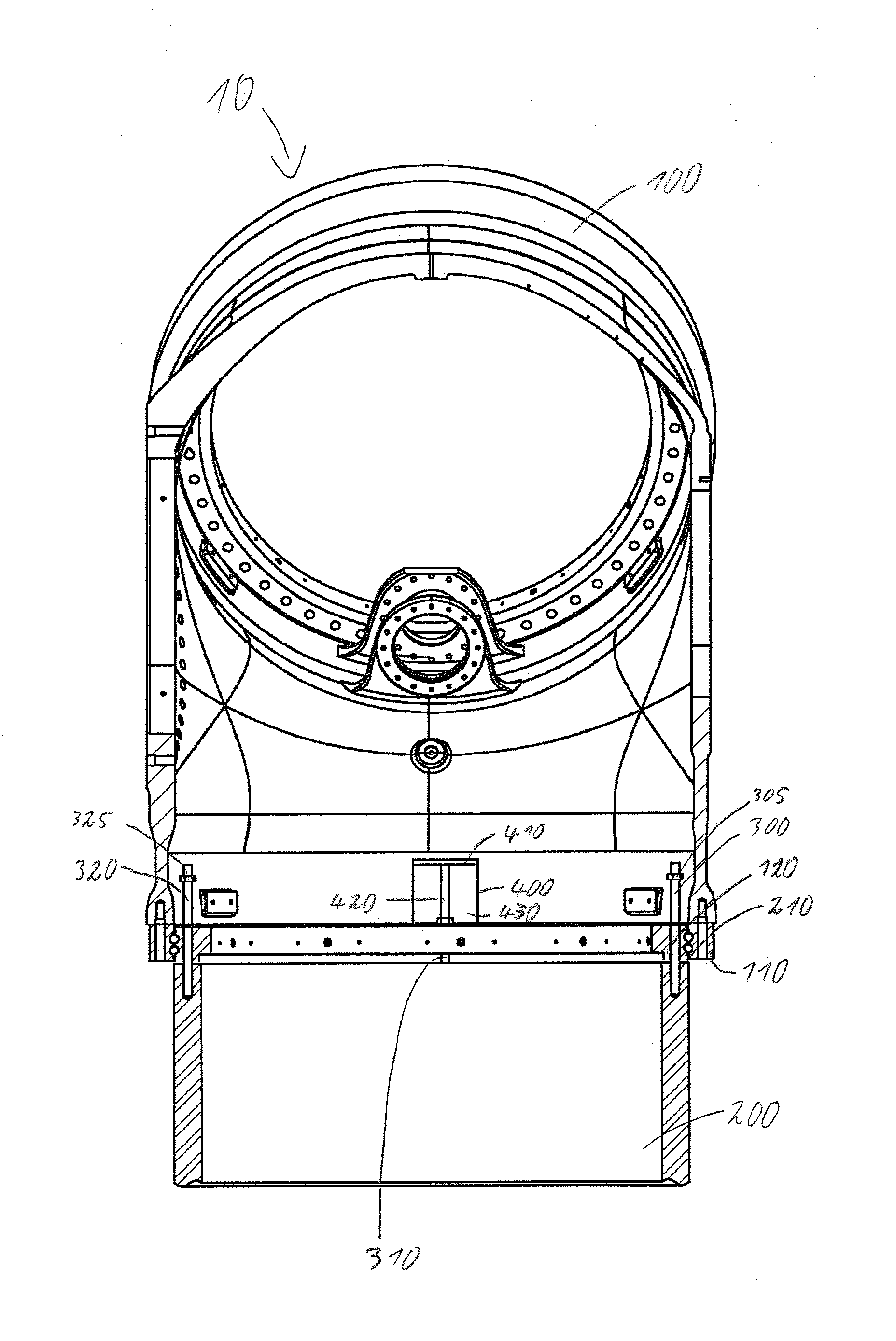
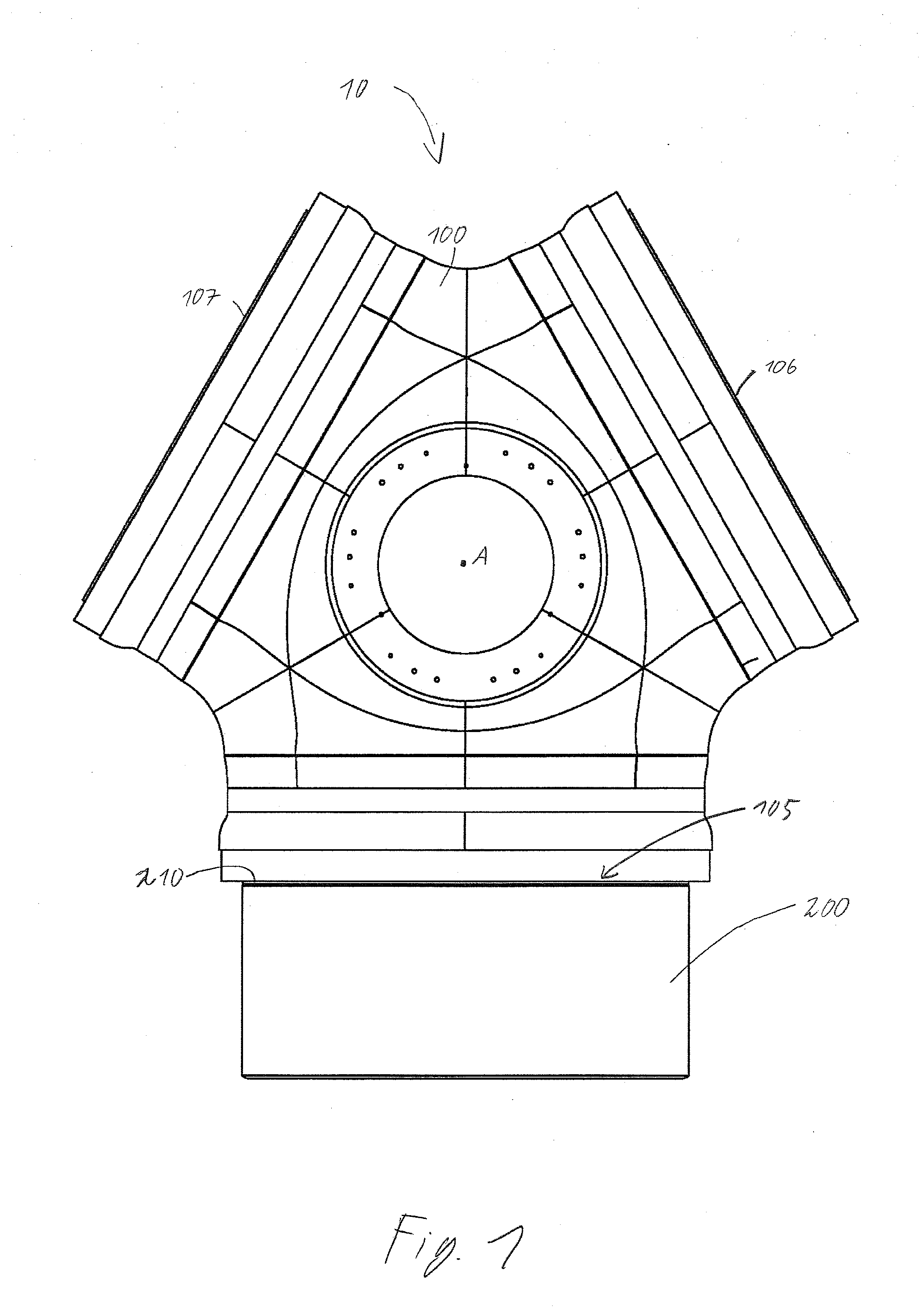
[0085]FIG. 1 shows a rotor blade arrangement 10 comprising a hub 100 and a rotor blade 200. Hub 100 is rotatable about an axis A.

[0086]Hub 100 has a hub flange 105 on which rotor blade 200 is mounted by means of a rotor blade flange 210. Hub 100 also has two other hub flanges 106, 107 to which other blades can be fastened. The invention shall now be described with reference to hub flange 105 only.

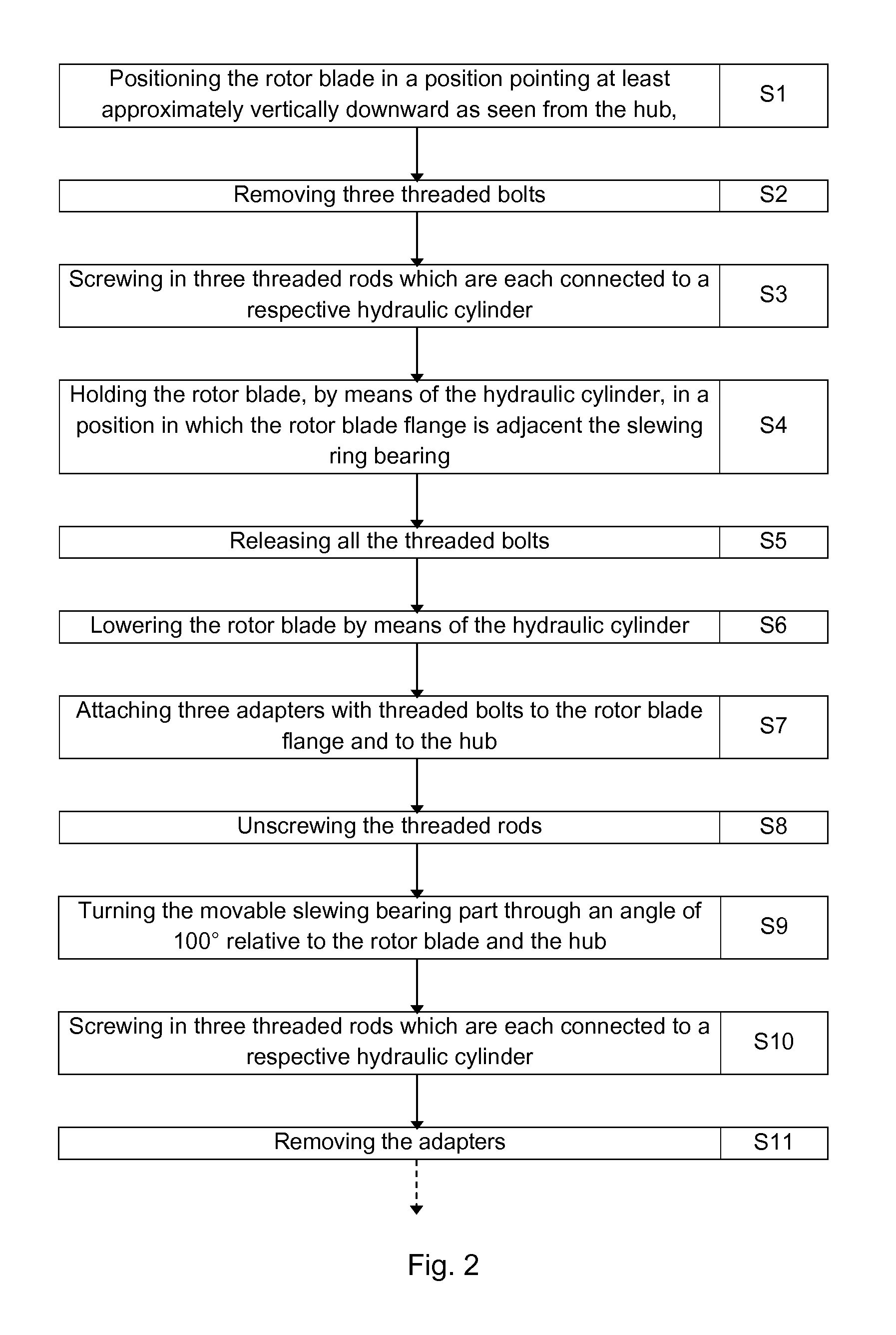
[0087]FIG. 2 shows an embodiment of the inventive method for servicing a wind turbine. FIG. 2 simultaneously shows embodiments of the inventive method of releasing a rotor blade, and developments of that method.

[0088]In step S1, a rotor blade on which maintenance or servicing work is to be carried out is brought into a position in which it points at least approximately vertically downward, as seen from the hub. This is done by turning the hub accordingly and applying a brake which is normally present in the wind turbine.

[0089]In step S2, three threaded bolts by which the rotor blade is fast...


PUM

PropertyMeasurementUnit
Angleaaaaaaaaaa
Angleaaaaaaaaaa
Lengthaaaaaaaaaa

Abstract

The invention relates to a method of servicing wind turbines having a hub containing a slewing ring bearing to which a rotor blade is fastened such that the pitch angle is adjustable. The rotor blade is brought into a position pointing vertically downward, lowered by means of threaded rods and hoisting means and attached suspendingly to the hub. The slewing ring bearing is then turned. The rotor blade is then hoisted again and fastened to the slewing ring bearing.

Description

BACKGROUND OF THE INVENTION[0001]The invention relates to wind turbines with rotor blade adjustment (also called pitch control or pitch adjustment). Such wind turbines have a rotor blade bearing for their adjustable rotor blade—said bearing also being called a slewing ring bearing. The invention relates in particular to the servicing of such wind turbines.[0002]Wind turbines typically have a rotor with a hub on which a plurality of rotor blades are mounted in most cases. In order to adjust the pitch angle of a respective rotor blade, a blade adjustment means is usually provided. This may comprise a slewing ring whose movable part is connected via a rotary bearing to the hub and is thus rotatable about a longitudinal axis of the blade with respect to the hub. The respective rotor blade is fastened to the movable part and is thus likewise rotatable about its longitudinal axis and adjustable in pitch with respect to the hub.[0003]Such slewing rings of the kind used in wind turbines gen...

Claims


Application Information

Patent Timeline
IPC IPC(8): F03D11/00B23P6/00B23P11/00
CPCY10T29/49721F03D1/003F05B2260/79Y10T29/49318Y02E10/72Y10T29/49316F03D80/50
Inventor HOLLING, JOCHEN
Owner VESTAS WIND SYST AS
Why Eureka
Try Eureka