Biosensor device and manufacturing method thereof

a biosensor and manufacturing method technology, applied in the field of biosensor devices, can solve the problems of high cost, high cost, and high cost of conventional biosensors, and achieve the effect of reducing the cost of manufacture and operation

Inactive Publication Date: 2012-06-07
ELECTRONICS & TELECOMM RES INST
View PDF4 Cites 11 Cited by
  • Summary
  • Abstract
  • Description
  • Claims
  • Application Information

AI Technical Summary

Benefits of technology

[0016]Without employing a reader, the biosensor device of the present invention comprises only a sensor element that makes it possible to determine the quantity of a target molecule in a liquid biosample with the naked eye. Accordingly, the biosensor device allows the user to quantitatively analyze a target molecule in situ with promptness and convenience, and enjoys the advantage of cutting back on the expenses incurred in the manufacture and operation of the reader.

Problems solved by technology

In an optical biosensor, for example, an expensive optical system such as an optical scanner is employed to detect the signal of a luminescent.
Since such a reader is difficult to embody into a cheap, portable system, conventional biosensors are problematic in terms of the user's convenience or accessibility, the rapidity of diagnosis, and cost.

Method used


Image

  • Biosensor device and manufacturing method thereof
  • Biosensor device and manufacturing method thereof
  • Biosensor device and manufacturing method thereof

Examples


Embodiment Construction

[0022]Reference now should be made to the drawings, in which the same reference numerals are used throughout the different drawings to designate the same or similar components.

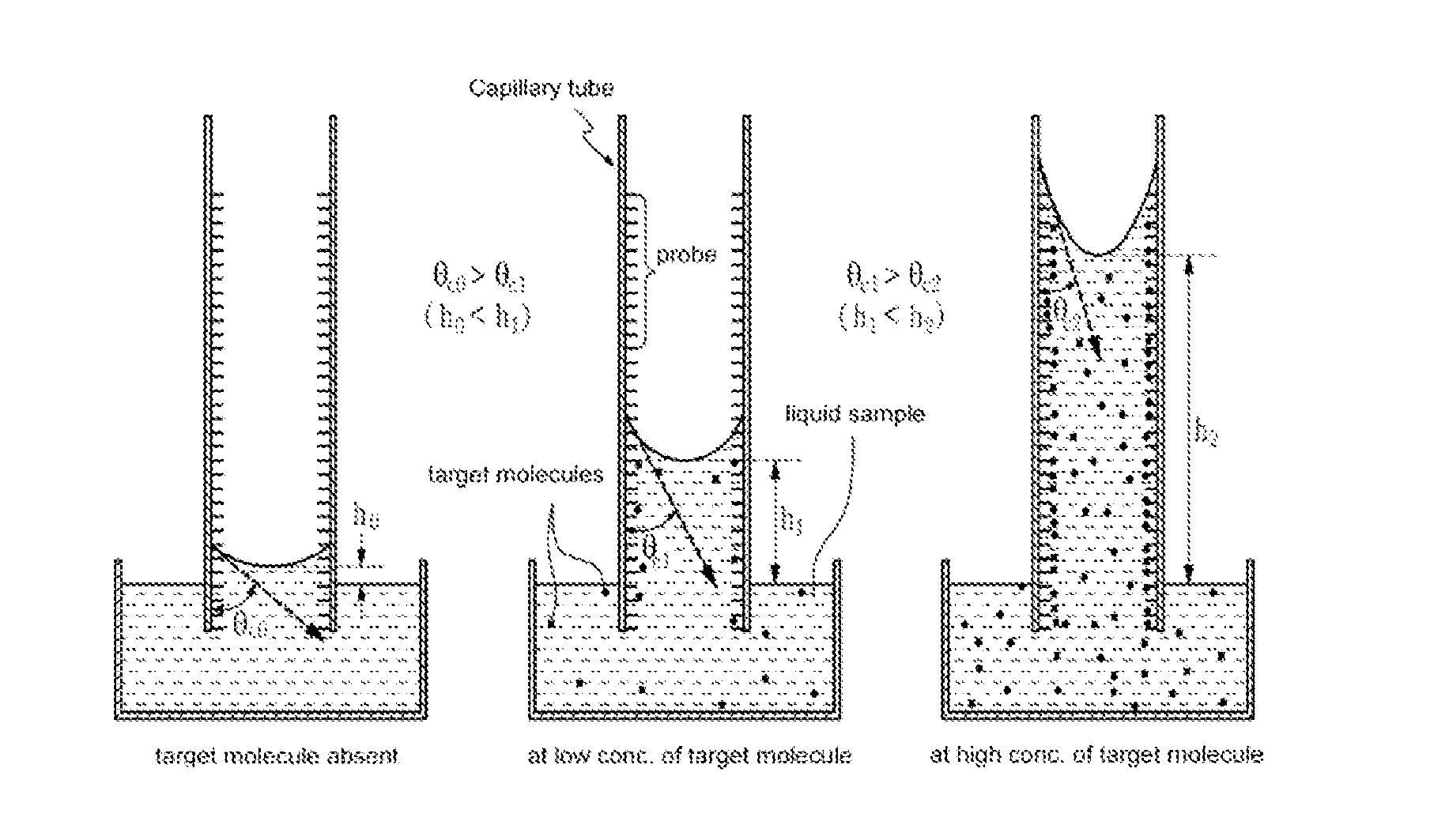
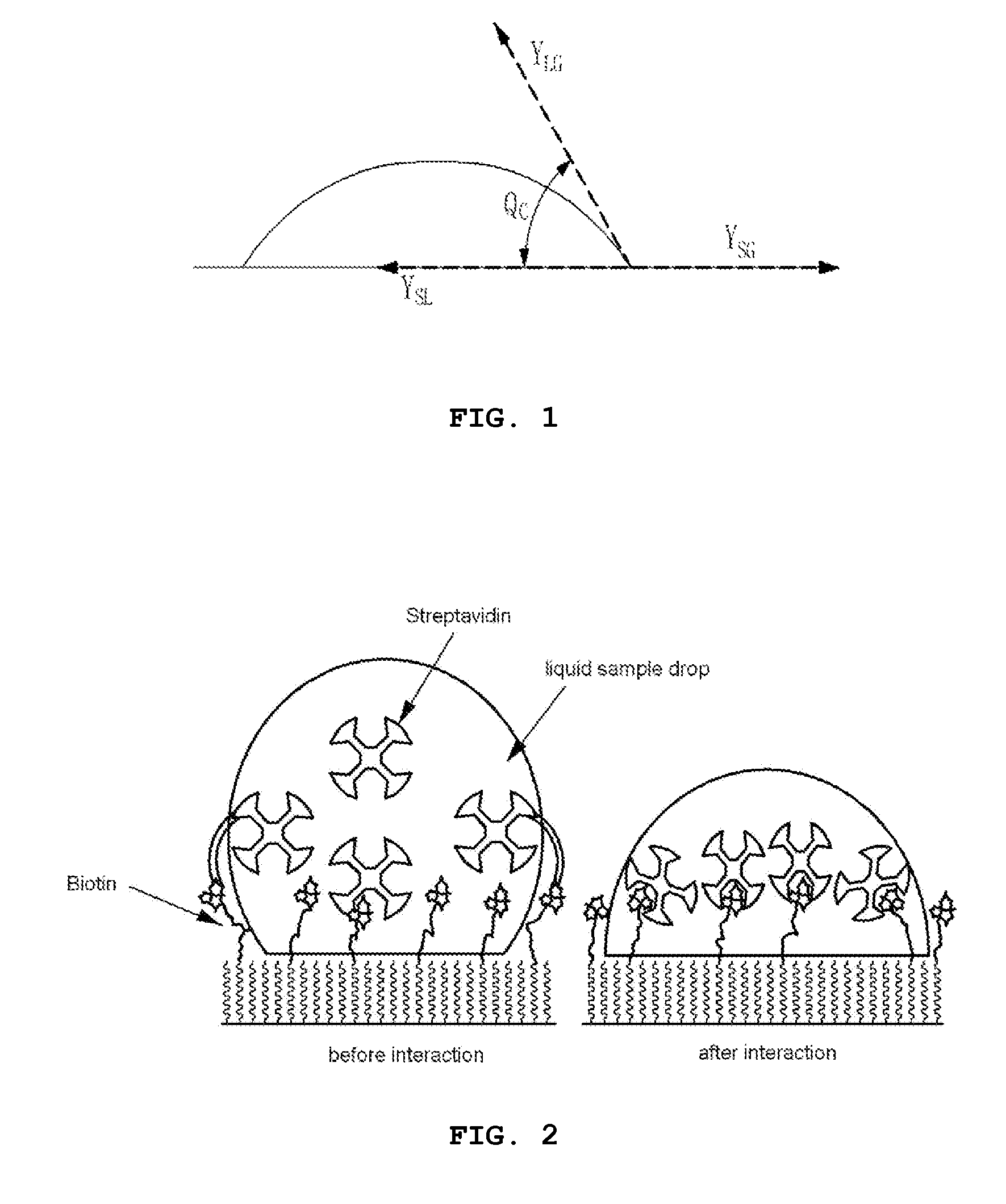
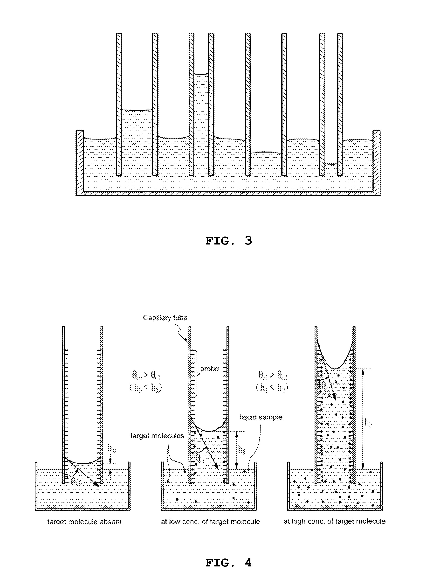
[0023]The biosensor device according to the present invention comprises a capillary tube with probe molecules immobilized on the inner wall surface thereof; and a liquid sample containing target molecules filled in the capillary tube, characterized in that a contact angle between the inner wall surface of the capillary tube and the liquid sample changes because of the specific interaction between the probe molecules and the target molecules, which leads, in turn, to a change in the height of the liquid sample in the capillary tube.

[0024]As used herein, the term “capillary tube” refers a tube which is thin and long enough to allow a capillary phenomenon.

[0025]The capillary phenomenon is a phenomenon whereby when a capillary tube is inserted in a liquid, the level of the liquid in the capillary rises or falls be...


PUM

PropertyMeasurementUnit
contact angleaaaaaaaaaa
heightaaaaaaaaaa
transparentaaaaaaaaaa

Abstract

Disclosed is a biosensor device, comprising: a capillary tube with probe molecules immobilized on the inner wall surface thereof, and a liquid sample containing target molecules, said biosensor device being characterized in that a contact angle between the inner wall surface of the capillary tube and the liquid sample changes because of the specific interaction between the probe molecules and the target molecules, which leads, in turn, to a change in the height of the liquid sample in the capillary tube.

Description

CROSS REFERENCE TO RELATED APPLICATION[0001]This application claims the benefit of Korean Patent Application No. 10-2010-0123542, filed Dec. 6, 2010, which is hereby incorporated by reference in its entirety into this application.BACKGROUND OF THE INVENTION[0002]1. Technical Field[0003]The present invention relates to a biosensor device useful for quantitatively determining a target molecule in a liquid sample with the naked eye, which is based on the fact that a contact angle between the inner wall surface of the capillary tube and the liquid sample changes because of the specific interaction of the probe molecules with the target molecules, which leads, in turn, to a change in the height of the liquid sample in the capillary tube. Also, the present invention is concerned with a method for manufacturing the same.[0004]2. Description of the Related Art[0005]Most biosensors for detecting specific target biomolecules (proteins, enzymes, DNAs, etc.) in liquid biosamples have probe mole...

Claims


Application Information

Patent Timeline
Patent Type & Authority Applications(United States)
IPC IPC(8): G01N33/53C12M1/34G01N33/82
CPCG01N33/54366C12Q1/6825C12Q1/6834G01N33/487G01N33/5302G01N33/5308
Inventor PARK, CHAN-WOOYANG, JONG-HEONAH, CHIL-SEONGKIM, WAN-JOONGAHN, CHANG-GEUNSUNG, GUN-YONG
Owner ELECTRONICS & TELECOMM RES INST
Why Eureka
Try Eureka