Apparatus to determine coefficient of friction

Inactive Publication Date: 2012-06-14
DOW GLOBAL TECH LLC
View PDF14 Cites 8 Cited by
  • Summary
  • Abstract
  • Description
  • Claims
  • Application Information

AI Technical Summary

Benefits of technology

[0031]wherein S1 is located between R1 and R2 to form a wrap angle (θ),

Problems solved by technology

Presently there are no suitable solutions for on-line, or at-line, COF measurements in the film industry.
This test method does not provide the COF or slip behavior of the whole roll of film.
This is a lab scale method, and not applicable to “on-line” measurements.
Additionally, the design showed a wrap angle of greater than, or equal to, 180°, which is not suitable for a continuous “on-line” or “at-line” process using a film web, since a high wrap angle will produce a high web tension, which may cause defects within the film or sheet roll, such as static charge and blocking effects.
For example, a film or sheet may wrinkle, and cause the roll to collapse when the film or sheet is tightly wound.
This described method is not applicable for a continuous “on-line” determination of COF.
Such a device is not suitable for continuous “on-line” or “at-line” measurements of COF.
These devices are not used to measure the coefficient of friction, and in most cases, do not provide sufficient accuracy for measuring the coefficient of friction.
This method is not easily adaptable to an “on-line” or “at-line” process.
Although described as an in-situ device, the design is not valid for a continuous film web process.
This large wrap angle cannot be used in an “on-line” or “at-line” apparatus due to the formation of wrinkles in the film web, and the large wrap angle may also cause excessive tension when winding the films.
This apparatus, as described, is not easily adaptable to a continuous production environment.
The apparatus, as described, is a stand alone unit, and the design is not practical for used in a continuous production environment.

Method used


Image

  • Apparatus to determine coefficient of friction
  • Apparatus to determine coefficient of friction
  • Apparatus to determine coefficient of friction

Examples


Embodiment Construction

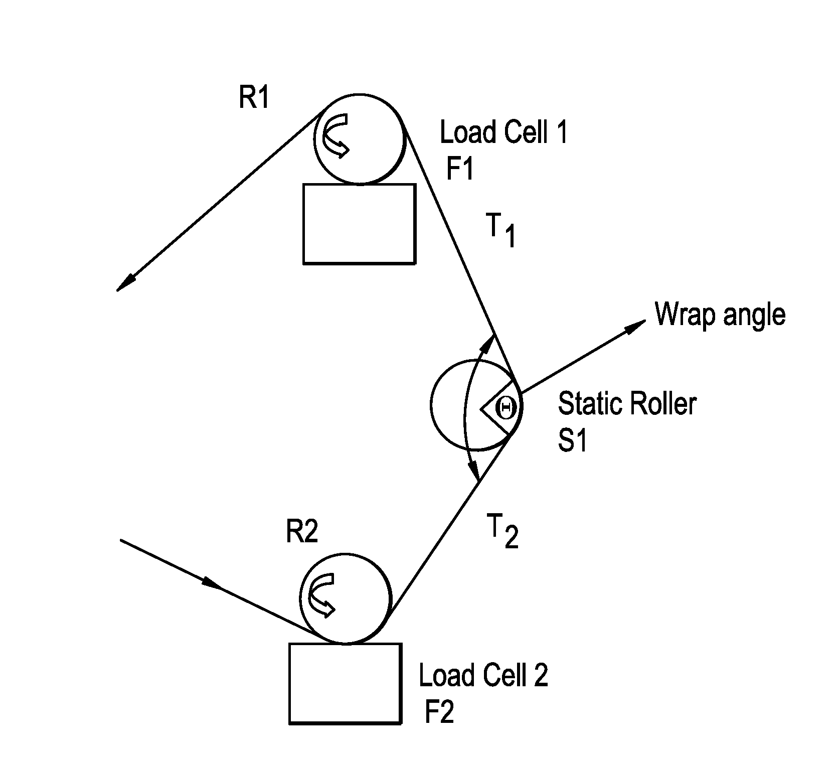
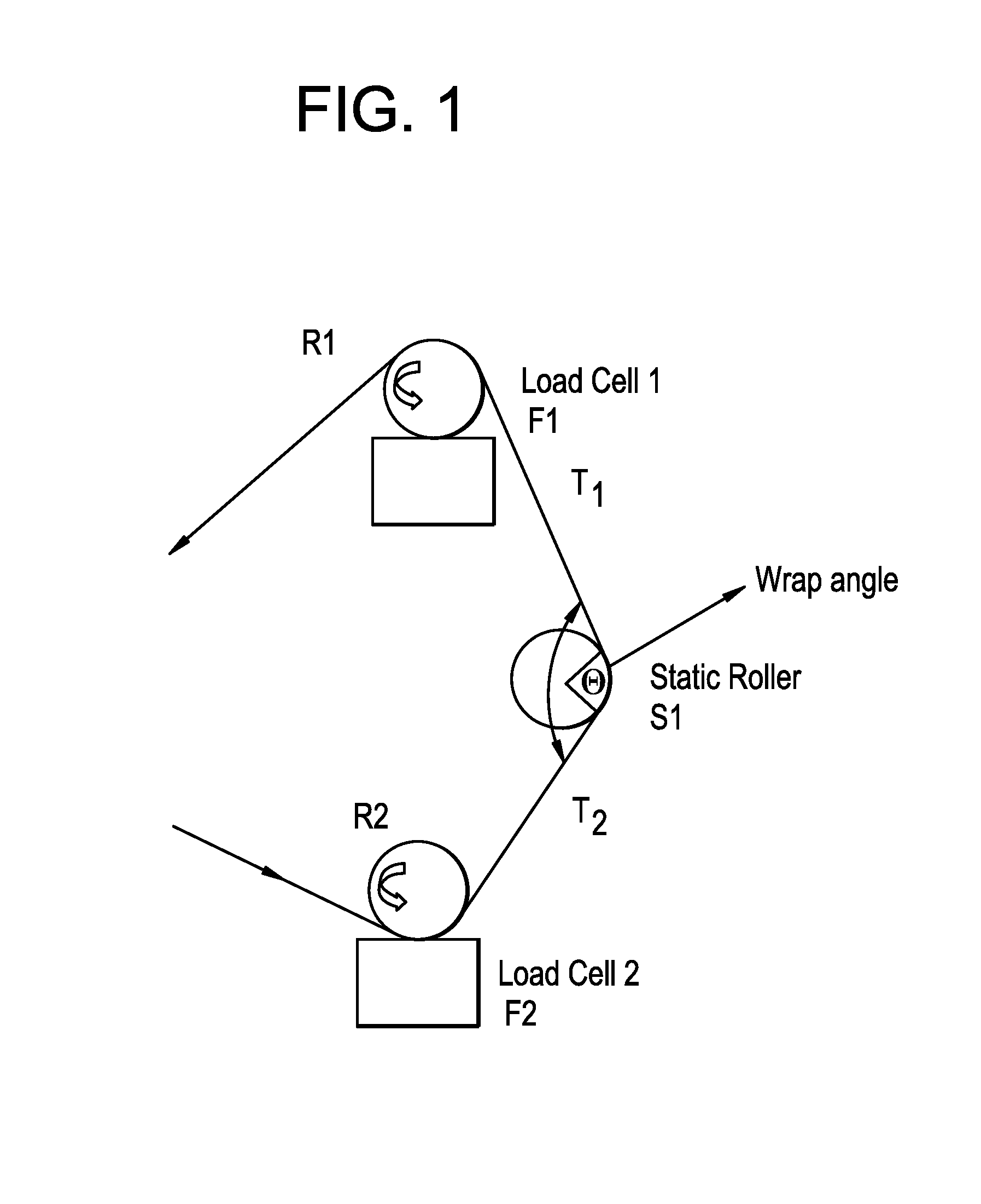
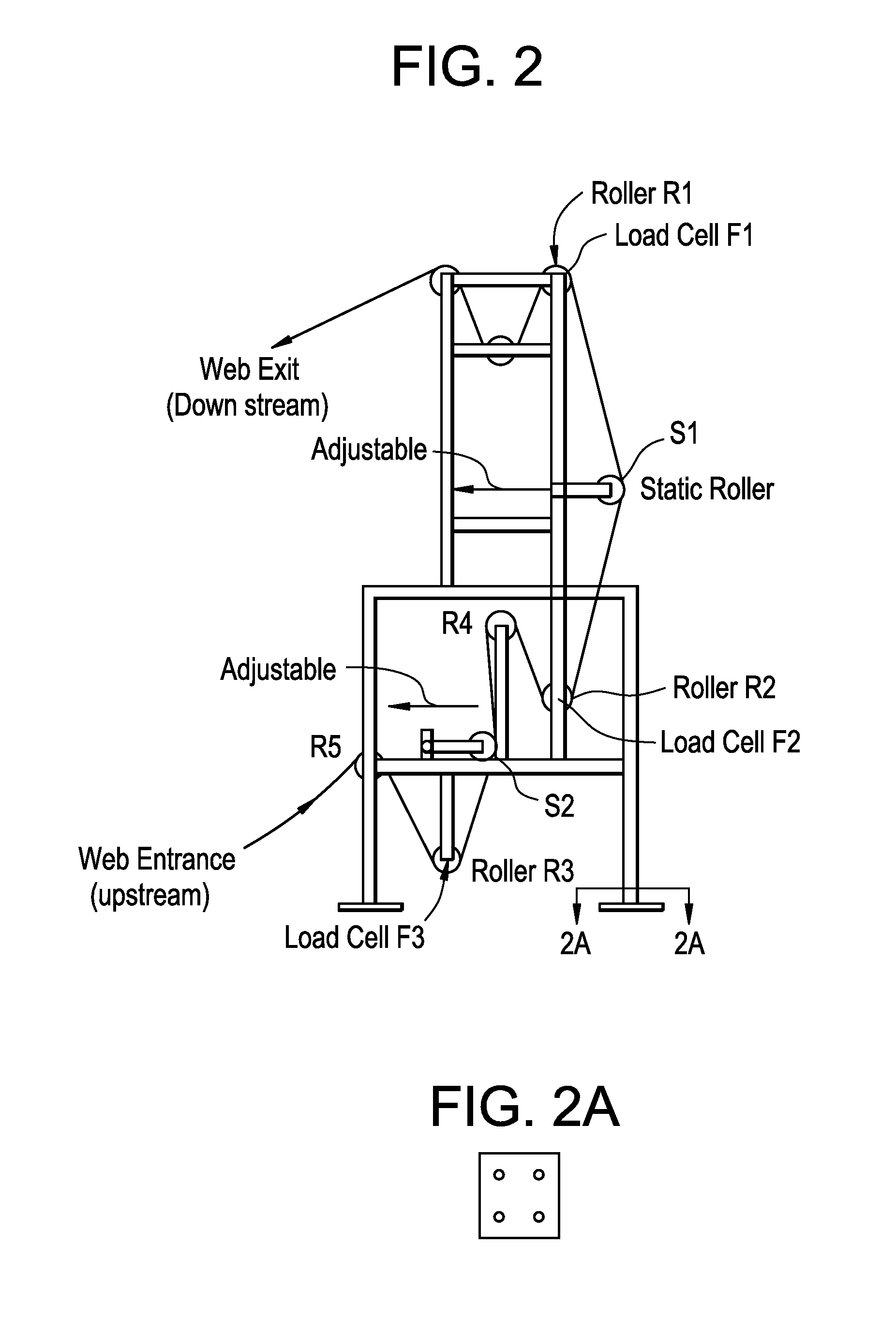
[0038]The invention provides a method for the continuous determination of the coefficient of friction (dynamic and / or static) of a material. In particular, the coefficient of friction of whole rolls of films or sheets can be determined, as the films or sheets are being used in a fabrication process. The apparatus can also be used to determine the unwinding force (or pull force) of the roll of film or sheet. Further, the apparatus can be used to measure a film COF “on-line” or “at line” during a blown film process, a cast film or sheet process, an extrusion coating, a lamination process, or a form fill and sealing (FFS) process.

[0039]The apparatus is particularly suited for an “on-line” or “at-line” blown film process, and a slitter rewinding process. The apparatus is also sensitive enough to detect the defects in the film. The apparatus is particularly suited for operation with an existing film or sheet line, which has an external drive unit. Optionally, a drive unit to wind and unw...


PUM


Abstract

The invention provides an apparatus for the continuous measurement of the dynamic coefficient of friction and / or static coefficient of friction of a material, which comprises at least the following: A) two rotating rollers, R1 and R2, B) one roller S1, C) optionally, one static roller S2, D) two sets of force detectors, F1 and F2, and wherein S1 is located between R1 and R2 to form a wrap angle (?), and wherein the wrap angle (?) is less than 90°, and wherein F1 is attached to R1, and F2 is attached to R2. The invention also provides an apparatus for the continuous measurement of the coefficient of friction (dynamic and / or static) and the pull force of a material, which comprises at least the following: A) two rotating rollers, R1 and R2, B) three rollers, R3, R4 and R5, C) one roller S1, D) optionally, one static roller S2, E) three sets of force detectors, F1, F2 and F3, and wherein S1 is located between R1 and R2 to form a wrap angle (?), and wherein the wrap angle (?) between R1 and R2 is less than 90°, and wherein R3, R4 and R5, are each located upstream from R2; and wherein F1 is attached to R1, F2 is attached to R2, and F3 is attached to R3.

Description

REFERENCE TO RELATED APPLICATIONS[0001]This application claims the benefit of U.S. Provisional Application No. 61 / 233,307, filed on Aug. 12, 2009, and fully incorporated herein by reference.BACKGROUND OF THE INVENTION[0002]The invention relates to an apparatus for the continuous determination of the coefficient of friction (COF) of a material, and, in particular, the COF of a film or sheet. The invention also relates to the continuous determination of COF and pull force of a material, and in particular, of a film or sheet.[0003]There is a critical need for film suppliers and film converters, for films and sheets that have a consistent COF throughout the surface of the film and sheet. Presently there are no suitable solutions for on-line, or at-line, COF measurements in the film industry. The current worldwide procedure is to measure COF on different areas of the film, using a separate off-line procedure.[0004]One method that is currently used for determining the coefficient of frict...

Claims


Application Information

Patent Timeline
IPC IPC(8): G01N19/02
CPCG01N19/02G01N2203/0278G01N33/36G01N33/34
Inventor PHAM, HOANG T.BARTHLOME, ROGER B.
Owner DOW GLOBAL TECH LLC
Why Eureka
Try Eureka