Ball Screw Device

a technology of ball screw and screw body, which is applied in the direction of gearing, gearing elements, hoisting equipment, etc., can solve the problems of increasing torque, and achieve the effects of preventing temperature rise, reducing dynamic friction torque, and hardly increasing the total preload

Inactive Publication Date: 2012-06-14
NSK LTD
View PDF4 Cites 8 Cited by
  • Summary
  • Abstract
  • Description
  • Claims
  • Application Information

AI Technical Summary

Benefits of technology

[0029]According to the respective embodiments of the present invention, the invention is capable of providing the ball screw apparatus where cooling effect of the nut is made high as much as possible.
[0030]Further, according to the ball screw apparatus of an embodiment of the present invention, the nut is provided with the cooling section as well as a preload type of the nut is two-point contact preload in a tensile direction. Since whereas radial contraction acts in a direction of increasing the preload, axial contraction acts in a direction of decreasing the preload to the contrary, the total preload is hardly increased. Thus, even when the nut is contacted by cooling, the invention can provide the ball screw apparatus of which dynamic friction torque is less likely to increase. That is, the invention is able to prevent temperature rise in the ball screw apparatus invoked along with an increase in the dynamic friction torque. Consequently, the present invention allows offering the ball screw apparatus in which the cooling effect of the nut is made high as much as one can.
[0031]According to the ball screw apparatus of another embodiment of the present invention, defining in the above equation (A) a ratio (L / D) between the axial length L of the through hole and the diameter D of the through hole provides an ideal ball screw apparatus cope with both the cooling effect and the total cost efficiency, taking into account of heat transfer coefficient, a difference in temperature between the screw shaft and the coolant, and an area of surfaces contacting with the coolant in the screw shaft.
[0032]Further, according to the ball screw apparatus of still another embodiment of the present invention, an increase in preload torque is prevented when cooling the nut.
[0033]Furthermore, according to the ball screw apparatus of yet another embodiment of the present invention, the leakage of the coolant from a gap between the nut and the spacer is provided.

Problems solved by technology

The screw apparatus disclosed in Patent Document 1, however, produces heat contraction in the feed nut cooled by the heat exchanger, resulting in an increase in torque.

Method used


Image

  • Ball Screw Device
  • Ball Screw Device
  • Ball Screw Device

Examples


first embodiment

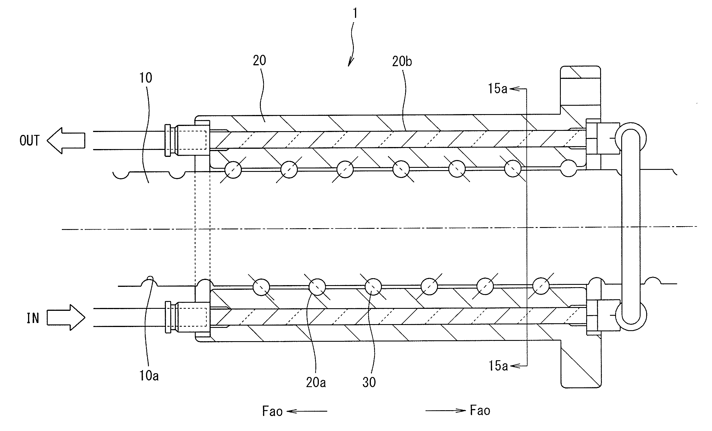
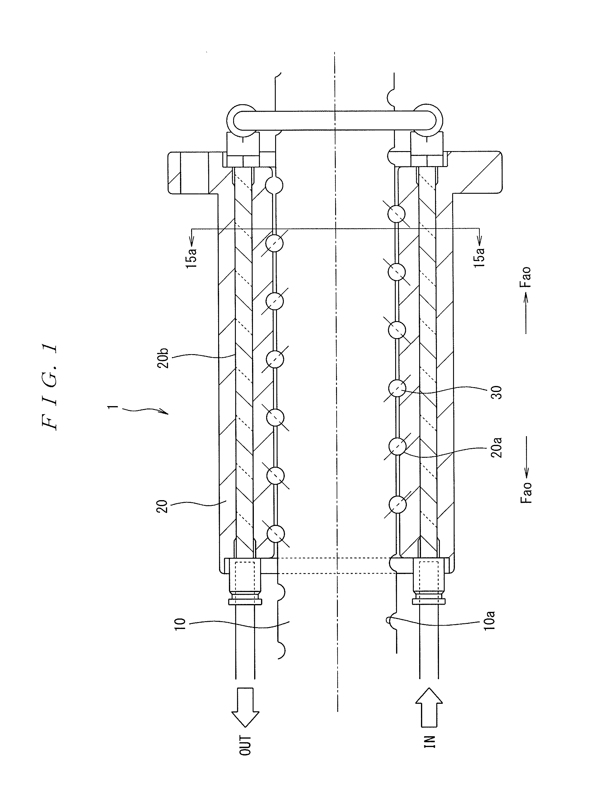
[0056]Hereinafter, a description will be made to a first embodiment of the ball screw apparatus according to the present invention with reference to the accompanying drawings. FIG. 1 is a sectional view in an axial direction showing a structure of the ball screw apparatus according to the present invention.

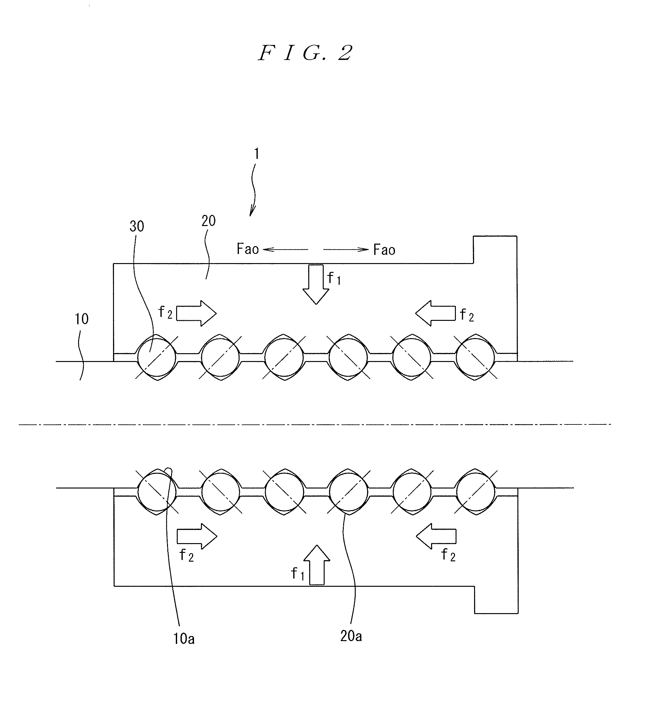
[0057]As shown in FIG. 1, the ball screw apparatus 1 according to the present invention embodiment includes a screw shaft 10 and a nut 20. The screw shaft 10 and the nut 20 are screwed with each other via a plurality of rolling members 30. The nut 20 is formed cylindrically to have an internal diameter larger than an external diameter of the screw shaft 10. A screw groove 20a is formed on an inner peripheral surface of the nut so as to face a screw groove 10a spirally formed on an outer peripheral surface of the screw shaft 10. Hereupon, the rolling members 30 are rollable in a rolling path formed by the screw groove 10a and the screw groove 20a.

[0058]Moreover, an axially penetra...

second embodiment

[0064]FIG. 3 is a drawing showing the ball screw apparatus according to the second embodiment. As shown in FIG. 3, whereas the first embodiment adopted the offset lead preload, as a preload style, the second embodiment adopts a double nut preload style in contradistinction thereto.

[0065]Specifically, as shown in FIG. 3, the ball screw apparatus 1 according to the second embodiment includes a first nut 20A, and a second nut 20B screwed with a common screw shaft 10 via the plurality of rolling elements 20, and a spacer 50. The spacer 50 is annularly formed to have the substantially same internal diameter as that of the first nut 20A and the second nut 20B, and prevents relative revolutions of the first nut 20A and the second nut 20B. Also, the provision of the spacer 50 applies the preload in the two-contact state preloaded with the preload Fa0 to the plurality of rolling elements 30 disposed between the respective screw grooves 21a and 22a of the first nut 20A and second nut 20B, and...

examples

[0066]Hereafter, a description will then be made to an example of the ball screw apparatus according the embodiments.

[0067]FIG. 4 is a graph showing a result obtained by driving the ball screw apparatus) see FIG. 1) of the first embodiment as a ball screw apparatus of the example 1, and by simultaneously measuring a value of temperature rise and torque of the nut when the nut is cooled in the course of driving.

[0068]FIG. 5 is a graph showing a result obtained by driving the ball screw apparatus of a comparative example 1 and by simultaneously measuring a value of temperature rise and torque when the nut is cooled in the course of driving.

[0069]A structure of the ball screw apparatus of the first embodiment and a comparative example 1 is shown in TABLE. 1, a driving condition of the first embodiment and the comparative example 1 is shown in TABLE. 2; and a cooling condition of the first embodiment and the comparative example 1 is shown in TABLE. 3.

[0070]Herein, the structure of the b...


PUM


Abstract

A ball screw apparatus is provided which is less likely to increase dynamic friction torque even when a nut is contracted by cooling, and in which cooling effect is made as high as possible and which does not invite excessive machining efficiency droop and increase in pressure loss. The ball screw apparatus includes a screw shaft, a nut screwed with the screw shaft via a plurality of balls, and a cooling section cooling the nut. The plurality of balls to which preload is applied in a two-point contact state, with a preload direction as a tensile direction, are disposed between a screw groove of the screw shaft and a screw groove of the nut. Or, a ratio of the axial length L of the through hole axially formed in the nut and the diameter D of the through hole axially formed in the nut is given by an equation “10≦L / D≦60”.

Description

BACKGROUND OF THE INVENTION[0001]1. Field of the Invention[0002]The present invention relates to a ball screw apparatus, in particular to a ball screw apparatus in which a nut is coolable.[0003]2. Related Art[0004]Conventionally, in a screw apparatus including a screw shaft and a feed nut which is screwed with the screw shaft and relatively rotatable, point contact or surface contact occurs during revolutions. On this account, a cooling section is provided at a heat source (e.g., the feed nut).[0005]As an example of the screw apparatus of this kind, there has been disclosed a screw apparatus where a cooling pipe through which coolant circulates is arranged in the feed nut as the cooling section (heat exchanger) (see e.g., Patent Document 1).[0006]Further, as technology of cooling the feed nut, there is the invention disclosed in Patent Document 2. Specifically, this technology flows coolant in a coolant through hole (hereafter, simply referred to as a through hole) to cool down the ...

Claims


Application Information

Patent Timeline
Patent Type & Authority Applications(United States)
IPC IPC(8): F16H25/22
CPCF16H57/0412F16H57/0497Y10T74/19749Y10T74/19707F16H25/2204Y10T74/19744
Inventor YAMAMOTO, KAZUHITOMINAKUCHI, JUNJINAGAI, YUTAKANOBUTOMO, MASAHIRO
Owner NSK LTD
Why Eureka
Try Eureka