Power conversion apparatus

a power conversion and power technology, applied in the direction of electrical apparatus construction details, printed circuit board receptacles, support structure mounting, etc., can solve the problems of limited space for installation, durability and reliability, and it is difficult to perform a work of high precision by bending work, etc., to achieve high versatility, vibration-proof and cooling

Inactive Publication Date: 2010-11-02
MITSUBISHI ELECTRIC CORP
View PDF16 Cites 8 Cited by
  • Summary
  • Abstract
  • Description
  • Claims
  • Application Information

AI Technical Summary

Benefits of technology

[0012]This invention has been made in order to solve the above problems in the prior-art apparatuses, and has for its object to obtain a power conversion apparatus which is installed on the mounting location of a vehicle or the like at a high versatility, and whose vibration-proofness and cooling effect are high.
[0017]In accordance with the power conversion apparatus according to this invention, the base includes the first fixation portion and second fixation portion which are respectively flat, and which are coupled to each other at the desired angle. Therefore, the power conversion apparatus can be endowed with the optimum configuration corresponding to the situation of the mounting space, and it is permitted to increase the versatility of the installation of the apparatus in the vehicle of many spatial restrictions, especially an engine room or the like. Moreover, the control circuit board is fixed with its first principal surface held in direct or indirect touch with the second fixation portion of the base. Therefore, the rigidity of the control circuit board becomes high, and the vibration-proofness and cooling effect thereof can be enhanced.
[0018]Besides, in accordance with the power conversion apparatus according to this invention, even in the case where the plurality of pairs of power modules and the plurality of control circuit boards are included, the power conversion apparatus can be endowed with the optimum configuration corresponding to the situation of the mounting space, and it is permitted to increase the versatility of the installation of the apparatus in the vehicle of many spatial restrictions, especially an engine room or the like. In addition, the rigidities of the control circuit boards become high, and the vibration-proofness and cooling effects thereof can be enhanced.

Problems solved by technology

Regarding an equipment which is installed on a vehicle, however, a space allowed for the installation is severely restricted.
Further, in the prior-art apparatus, the control circuit board for controlling the drives of the power modules (IPM drive circuit board) is fixed on a base side through a cover member, and any configurational consideration for enhancing vibration-proofness is not made.
Accordingly, a resonance point ascribable to the vibrations is inevitably existent, and displacements caused by the resonance of the printed circuit board attributed to the resonance frequency of the resonance point develop, so that electric components and electronic components packaged on the printed circuit board, or structural components are apprehended to damage or fall off.
Further, the prior-art apparatus has not a structure which emits heats generated by the electronic components, etc. packaged on the control circuit board, and it is problematic in durability and reliability.
In general, however, it is difficult to perform a work of high precision by the bending work.
In an assembling structure which requires a comparatively minute dimensional precision as in case of inserting the control signal pins of the power modules into holes provided in a printed circuit board, as in the power conversion apparatus which is installed on the vehicle, there is the problem that all the pins cannot be inserted due to dimensional deviations in some cases.

Method used


Image

  • Power conversion apparatus
  • Power conversion apparatus
  • Power conversion apparatus

Examples


embodiment 1

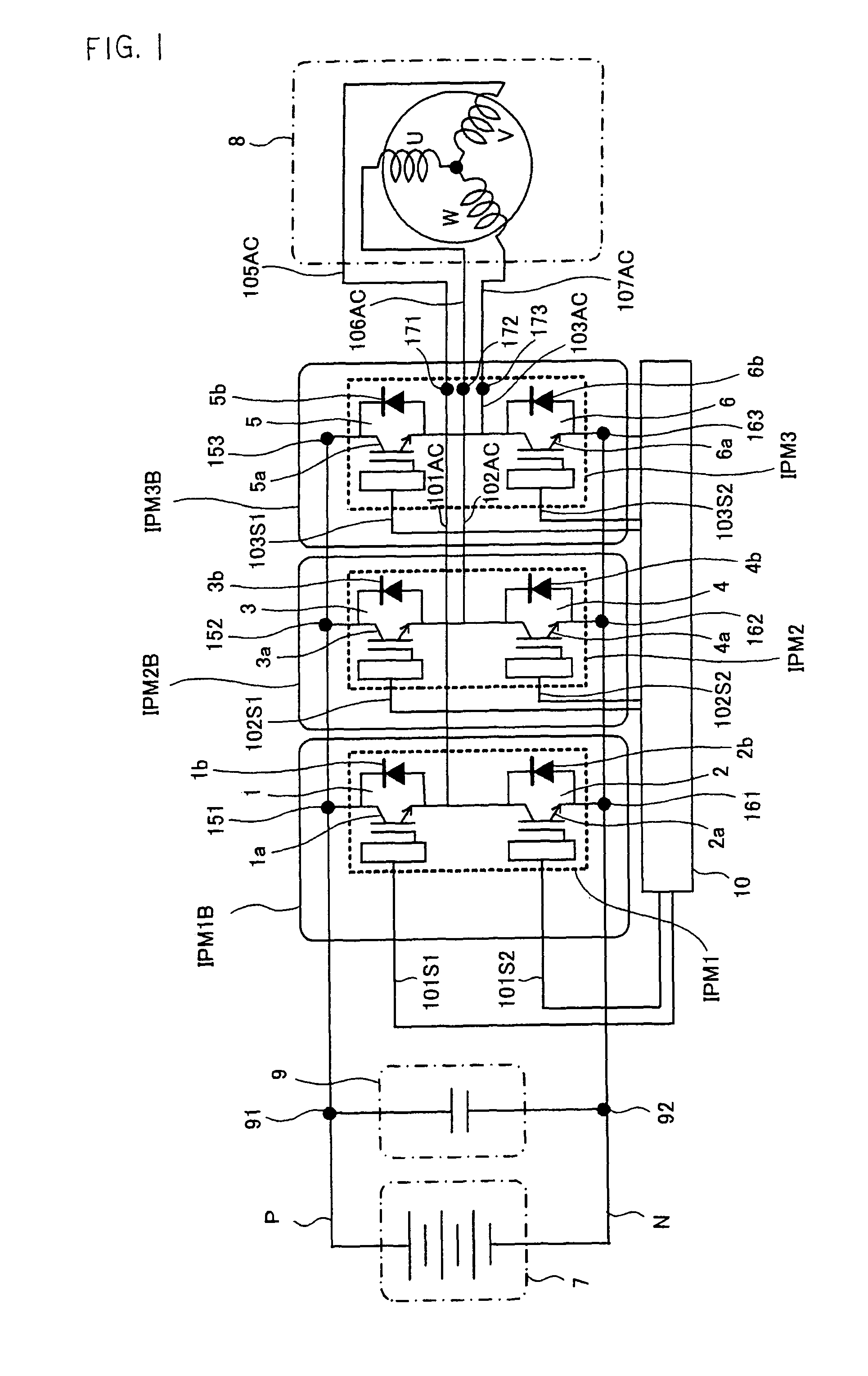
[0027]FIG. 1 is an explanatory diagram showing the schematic arrangement of a power conversion circuit. Referring to FIG. 1, a semiconductor element (Insulated Gate Bipolar Transistor: hereinbelow, abbreviated to “IGBT”) 1a in which a MOS field effect transistor and a bipolar transistor are combined into one chip, and a flywheel diode 1b are connected in parallel, thereby to constitute a pair of power semiconductor elements 1. Likewise, IGBTs 2a, 3a, 4a, 5a and 6a and flywheel diodes 2b, 3b, 4b, 5b and 6b corresponding to the IGBTs are connected in parallel, thereby to constitute pairs of power semiconductor elements 2, 3, 4, 5 and 6, respectively.

[0028]The power semiconductor elements 1, 3 and 5 form the upper arms of three-phase bridge circuits constituting the power conversion circuit, and the power semiconductor elements 2, 4 and 6 form the lower arms thereof, respectively. Besides, the power semiconductor elements 1 and 2, 3 and 4, and 5 and 6 are respectively connected in seri...

embodiment 2

[0050]FIGS. 4 and 5 show a power conversion apparatus according to Embodiment 2 of this invention, and FIG. 4 is a plan view of the apparatus, while FIG. 5 is a side view thereof.

[0051]Embodiment 2 consists in that two power modules IPM11 and IPM12, IPM21 and IPM22, or IPM31 and IPM32 forming one set are electrically connected in parallel, for each phase of the stator winding U, V or W of a three-phase brushless DC motor, so as to drive the motor which is a load of higher power.

[0052]Referring to FIGS. 4 and 5, the power modules IPM11 and IPM12, IPM21 and IPM22, and IPM31 and IPM32 form pairs, and they are fixed by screws 1411 and 1412, 1421 and 1422, and 1431 and 1432 with their bottom surfaces held in touch with the first fixation portion 110a of a base 110, respectively. The respective screws are clamped in threadable engagements with threaded holes which are provided in the first fixation portion 110a of the base 110.

[0053]The base 110 is configured of the first flat fixation po...

embodiment 3

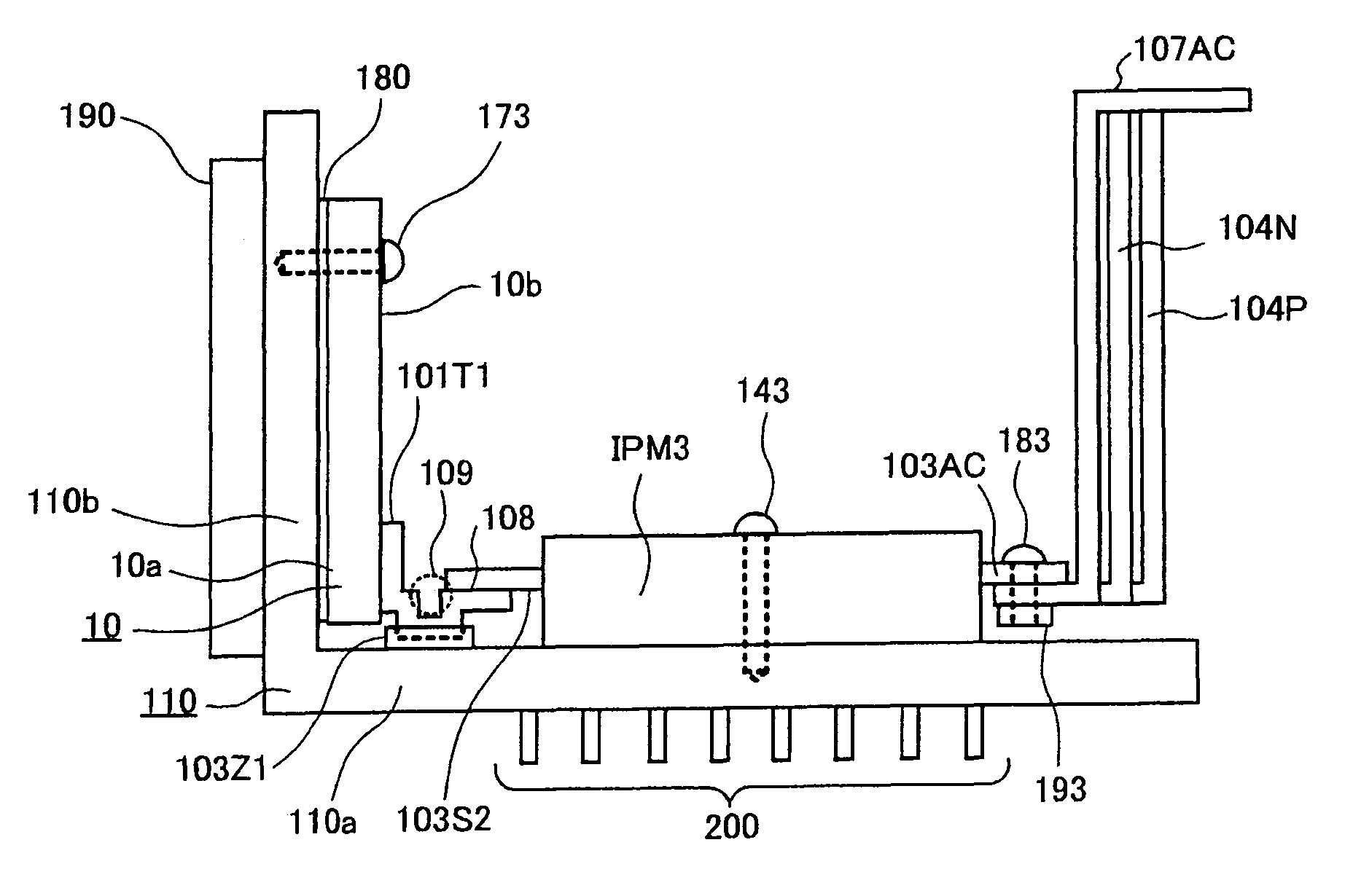
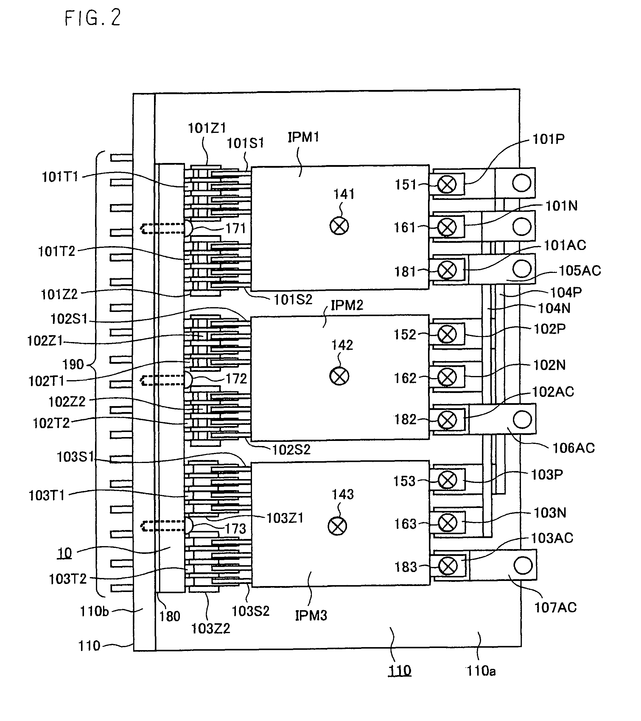
[0075]FIGS. 6 and 7 show a power conversion apparatus according to Embodiment 3 of this invention, and FIG. 6 is a plan view of the apparatus, while FIG. 7 is a side view thereof. Embodiment 3 consists in that one power module IPM1, IPM2 or IPM3 is arranged for the corresponding one of the stator windings of a three-phase brushless DC motor.

[0076]Referring to FIGS. 6 and 7, a control circuit board 10 has its first principal surface 10a bonded to the outer side of the second fixation portion 110b of a base 110 over the whole area by an adhesive 180, and it is fixed by screws 171, 172 and 173. Electronic components, electric components, etc. which constitute a control circuit for the switching controls of power semiconductor elements included in the power modules IPM1, IPM2 and IPM3 are packaged on the second principal surface 10b of the control circuit board 10.

[0077]Terminals 101T1 and 101T2, 102T1 and 102T2, and 103T1 and 103T2 which are packaged on the second principal surface 10b...


PUM


Abstract

A power conversion apparatus comprising a base which includes a first fixation portion and a second fixation portion that are coupled to each other at a desired angle, wherein power modules are fixed on the first fixation portion of the base, a control circuit board is fixed with its first principal surface held in direct or indirect touch with the second fixation portion of the base, and components constituting a control circuit are packaged on the second principal surface of the control circuit board. Owing to the configuration, a versatility for the installation of the power conversion apparatus on a vehicle becomes high, the vibration-proofness of the control circuit board is enhanced, and heats generated by the electronic components, etc. packaged on the control circuit board are sufficiently emitted.

Description

BACKGROUND OF THE INVENTION[0001]1. Field of the Invention[0002]This invention relates to a power conversion apparatus which controls an AC motor for driving, for example, a vehicle, and more particularly to the mechanical configuration thereof.[0003]2. Description of the Related Art[0004]In general, a power conversion apparatus for controlling the driving motor of a vehicle in a hybrid automobile, an electric automobile or the like includes as its principal constituents, power modules each of which includes power semiconductor elements for converting powers between DC and AC, a control circuit board on which components constituting a control circuit for controlling the power semiconductor elements of the power modules are packaged, a smoothing capacitor, and bus bars which electrically connect the power modules and the motor. The constituents are arranged and fixed in correspondence with the mounting structure of the vehicle.[0005]In such a power conversion apparatus, there has bee...

Claims


Application Information

Patent Timeline
Patent Type & Authority Patents(United States)
IPC IPC(8): H01R9/00
CPCH05K7/1432H05K7/14329
Inventor YAMABUCHI, HIROSHIKURAMOTO, YUJIMAEKAWA, HIROTOSHINISHIYAMA, RYOJI
Owner MITSUBISHI ELECTRIC CORP
Why Eureka
Try Eureka