
Explosives container and method

Active Publication Date: 2012-06-14
CRINUM IP
View PDF8 Cites 10 Cited by
  • Summary
  • Abstract
  • Description
  • Claims
  • Application Information

AI Technical Summary

Benefits of technology

[0008]It is an object of the invention to overcome or alleviate one or more of the

Problems solved by technology

The results achieved by the blast are greatly affected by the size and shape of the actual blast rock.
Since the boreholes drilled for pre-splitting are, in practice, the same size as those for production blasting the problem is created of how the correct, lesser, amount of explosives can be placed in the borehole at the correct depths for successful pre-splitting.
This is a relatively time consuming and labour intensive process involving the introduction of large quantities of filler material.
Placement and maintenance of this device in each deck can be problematic since the ensuing filler can damage or re-locate the booster and effectively separate it from the charge.
There are further problems if the borehole is completely or partially filled with water, as can often happen.
Even in stagnant water this process is less than ideal but in boreholes containing dynamic water it is extremely unreliable and the booster is frequently dislodged or the dynamic water may actually wash away the explosive charge before detonation can take place.
If the booster does not lodge successfully within the explosive charge or the charge is washed away then the result may be a misfire.
This is a very costly process as the borehole will have to be cleared and possibly re-drilled.
This is a serious drain on man hours and greatly increases the expense of mining an area.

Method used


Image

  • Explosives container and method
  • Explosives container and method
  • Explosives container and method

Examples


Embodiment Construction

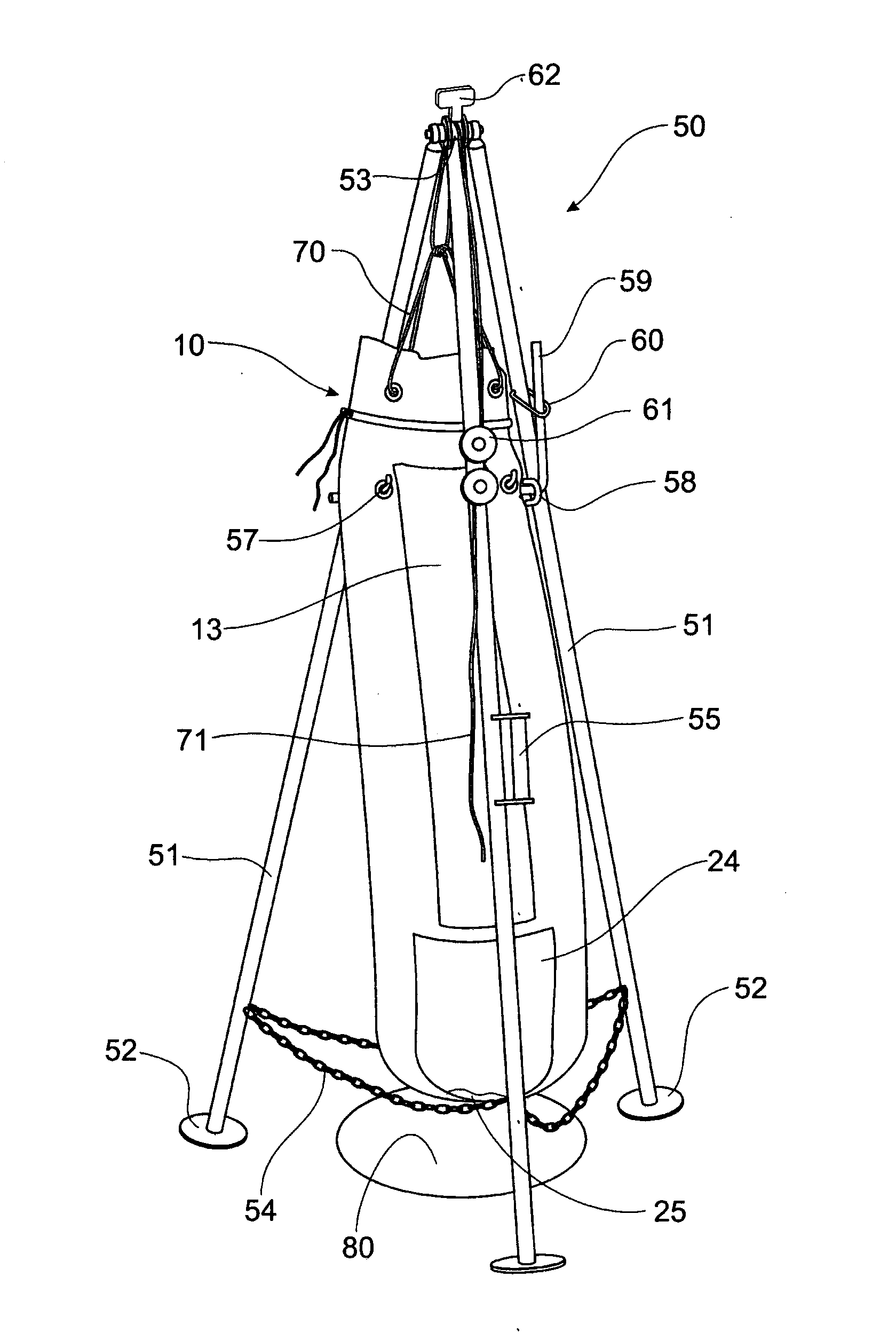
[0055]The terms “explosives booster” and “booster” as used herein encompass any kind of explosive device which can be employed to detonate a larger, generally more powerful, explosive charge. These devices are well known in the art and, generally, comprise a low energy explosive to increase the energy of an initiating explosive to a level sufficient to trigger explosion of the low sensitivity / high energy main explosive charge, such as ANFO. Non-limiting examples of such devices include compositions comprising RDX (cyclotrimethylenetrinitramine), PETN (pentaerythritol tetranitrate), TNT, various explosive emulsions and the like.

[0056]The term “detonator cord” as used herein may refer to any cord which is capable of transmitting sufficient energy to initiate explosion of the booster. The use of this term herein includes those cords having an explosive core of PETN or the like as well as electrical detonators which employ a length of wire or fuse of some kind which is subjected to an e...


PUM


Abstract

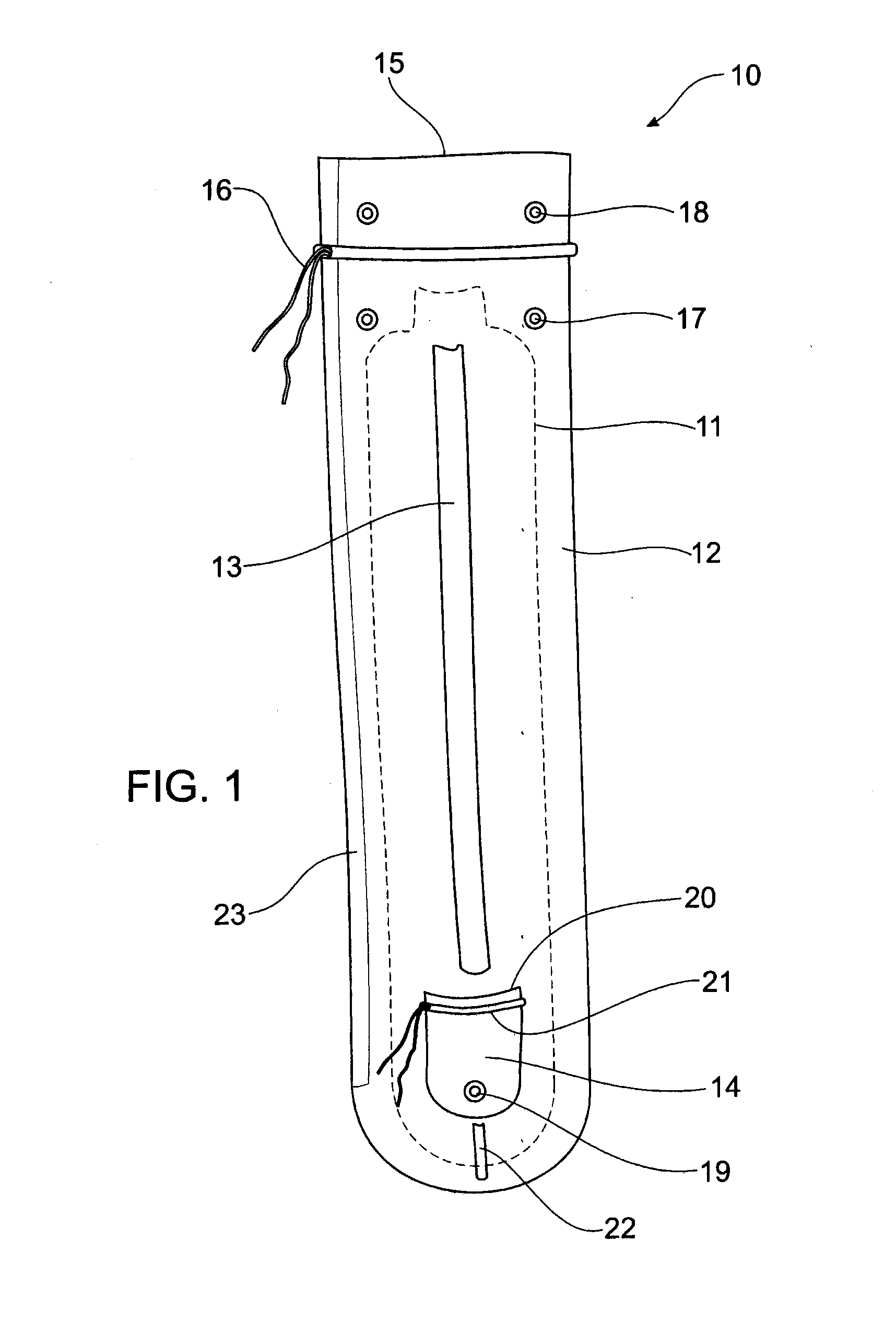
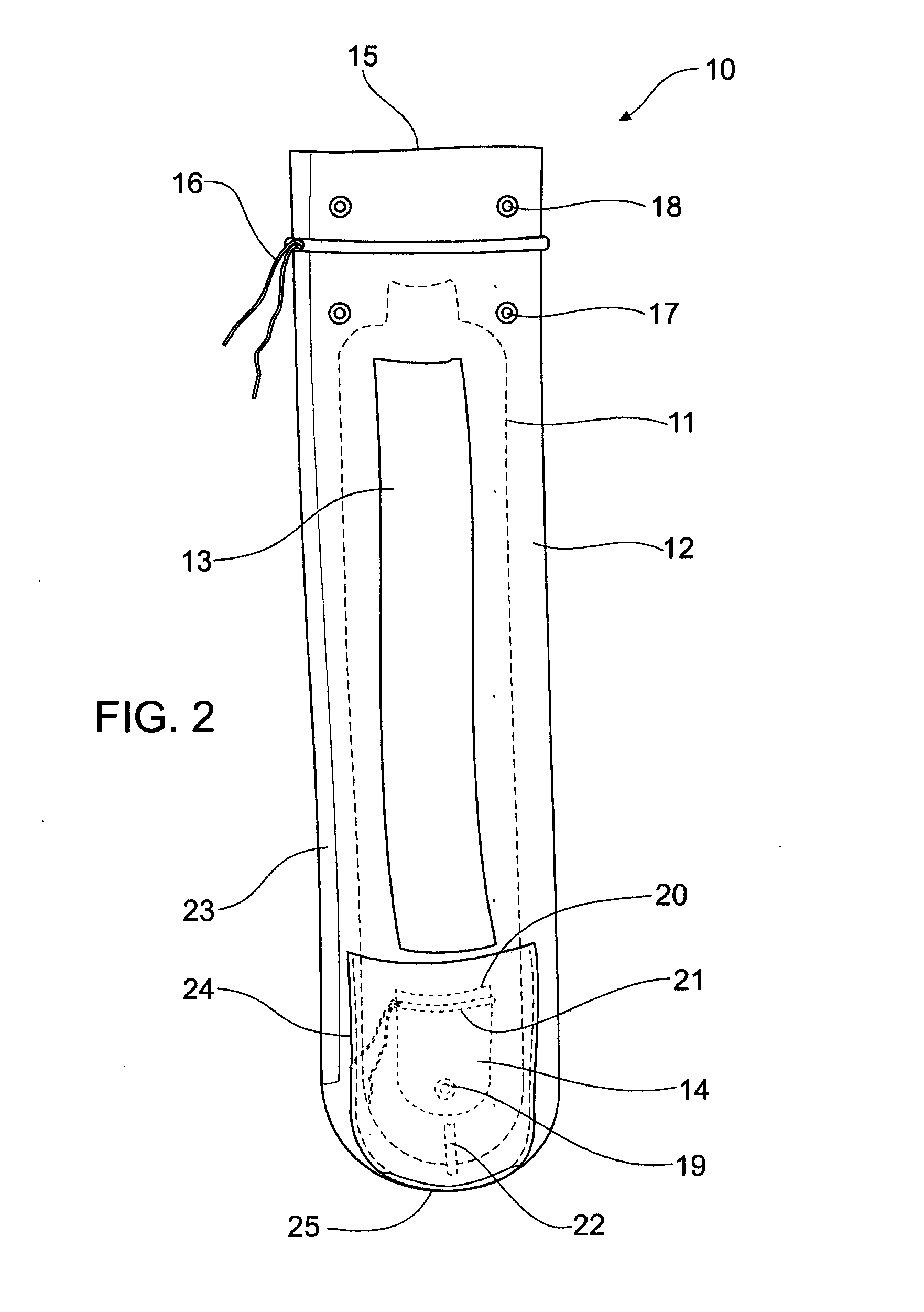
An explosives container comprising a flexible inner bag within a flexible outer bag, the outer bag comprising a first end and a second end and a booster compartment located on an external surface of the outer bag, adjacent the second end. An explosive composition can be located within the inner bag and, in use, the booster compartment contains an explosive booster and serves to maintain the explosive booster in close contact with the explosives composition. The explosives container further comprises an elongate sheath extending substantially between the first end and the second end of the outer bag and serving to house and protect a detonator cord from damage or dislodgement.

Description

FIELD OF THE INVENTION[0001]The present invention is concerned with an apparatus and method for containing and locating an explosive composition. More particularly, this invention relates to a container to hold explosive compositions and related initiating devices and a method of locating same in a borehole.BACKGROUND OF THE INVENTION[0002]In mining applications explosive compositions often need to be placed in boreholes / blastholes in defined depths and amounts. This helps ensure that the blast rock is broken down in the desired manner leaving rubble and muck pile or fragmentation which is as large as is manageable for more efficient and economical removal / further processing.[0003]The results achieved by the blast are greatly affected by the size and shape of the actual blast rock. The practice of pre-splitting is commonly used to create relatively steep and smooth highwall faces for improved stability control over subsequent blasting. The pre-splitting process involves drilling a r...

Claims


Application Information

Patent Timeline
IPC IPC(8): F42D3/00F42B3/087
CPCF42D1/16F42B3/087
Inventor MARTIN, MICHAEL JOHN
Owner CRINUM IP
Learn More