Method for measuring sea waves by means of ultrasonic waves, as well as sea wave measuring system

a technology of ultrasonic waves and sea waves, applied in direction finders using ultrasonic/sonic/infrasonic waves, instruments, reradiation, etc., can solve the problems of reducing the accuracy and reliability of observation data, limited use, etc., and achieve accurate measurement, accurate measurement, and accurate measurement

Inactive Publication Date: 2012-06-14
HITACHI ZOSEN CORP +2
View PDF3 Cites 21 Cited by
  • Summary
  • Abstract
  • Description
  • Claims
  • Application Information

AI Technical Summary

Benefits of technology

[0015]According to the first and second aspects, ultrasonic waves are emitted from the at least three ultrasonic transmitters on or in the vicinity of the seabed toward the sea surface, and the ultrasonic waves are received by the ultrasonic receiver provided below the sea surface on the floating body. When the one-way propagation time of the ultrasonic waves is detected to measure the distances between the floating body and the ultrasonic transmitters, wave heights are measured by high-pass filtering the measured distance data, that is, removing the long-term fluctuation components to extract only the short-term fluctuation components not containing the influence of seawater. Thus, the measurement is not affected by the sea surface as compared to the related art in which ultrasonic waves are transmitted from the transmitter / receiver on the seabed toward the sea surface and are reflected by the sea surface to measure wave heights. That is, even when waves are high, the wave heights can be accurately measured, so that an unmeasurable state is hardly produced.
[0016]According to the third and fourth aspects, ultrasonic waves are transmitted into the sea from the ultrasonic transmitter / receiver provided below the sea surface on the floating body on the sea surface, and the ultrasonic waves are received by the ultrasonic transmitter / receiver from the sound wave relay device on or in the vicinity of the seabed. When the round-trip propagation time of the ultrasonic waves is detected to measure the distance between the floating body and the sound wave relay device, wave heights are measured by high-pass filtering the measured distance data, that is, removing the long-term fluctuation components to extract only the short-term fluctuation components not containing the influence of seawater. Thus, the measurement is not affected by the sea surface as compared to the related art in which ultrasonic waves are transmitted from the ultrasonic transmitter / receiver on the seabed toward the sea surface and are reflected by the sea surface to measure wave heights. That is, even when waves are high, the wave heights can be accurately measured, so that an unmeasurable state is hardly produced.
[0017]According to the fifth and sixth aspects, ultrasonic waves are transmitted into the sea from below the sea surface from the floating body on the sea surface, and the ultrasonic waves are received with the time of emission by the ultrasonic transmitter / receiver of the floating body from the at least three ultrasonic relay devices on or in the vicinity of the seabed. When the one-way propagation time of the ultrasonic waves is detected to measure the distances between the floating body and the ultrasonic relay devices, wave heights are measured by high-pass filtering the measured distance data, that is, removing the long-term fluctuation components to extract only the short-term fluctuation components not containing the influence of seawater. Thus, the measurement is not affected by the sea surface as compared to the related art in which ultrasonic waves are transmitted from the ultrasonic transmitter / receiver on the seabed toward the sea surface and are reflected by the sea surface to measure wave heights. That is, even when waves are high, the wave heights can be accurately measured, so that an unmeasurable state is hardly produced.

Problems solved by technology

The under-water pressure type wave meter can be used in shallow waters but has a limited use in very deep waters with a lower sensitivity to short-period waves since the movement of water particles due to sea surface waves does not reach the seabed.
Thus, when the under-water pressure type wave meter is used, observed waveforms are obtained through a low-pass filter, inevitably reducing the accuracy and reliability of observation data.

Method used


Image

  • Method for measuring sea waves by means of ultrasonic waves, as well as sea wave measuring system
  • Method for measuring sea waves by means of ultrasonic waves, as well as sea wave measuring system
  • Method for measuring sea waves by means of ultrasonic waves, as well as sea wave measuring system

Examples


first embodiment

[0027]The following will describe a method for measuring sea waves using ultrasonic waves and a sea wave measuring system according to a first embodiment of the present invention.

[0028]In the first embodiment, wave heights especially in very deep waters, in addition to coastal waters, are measured using ultrasonic waves emitted (transmitted) into water.

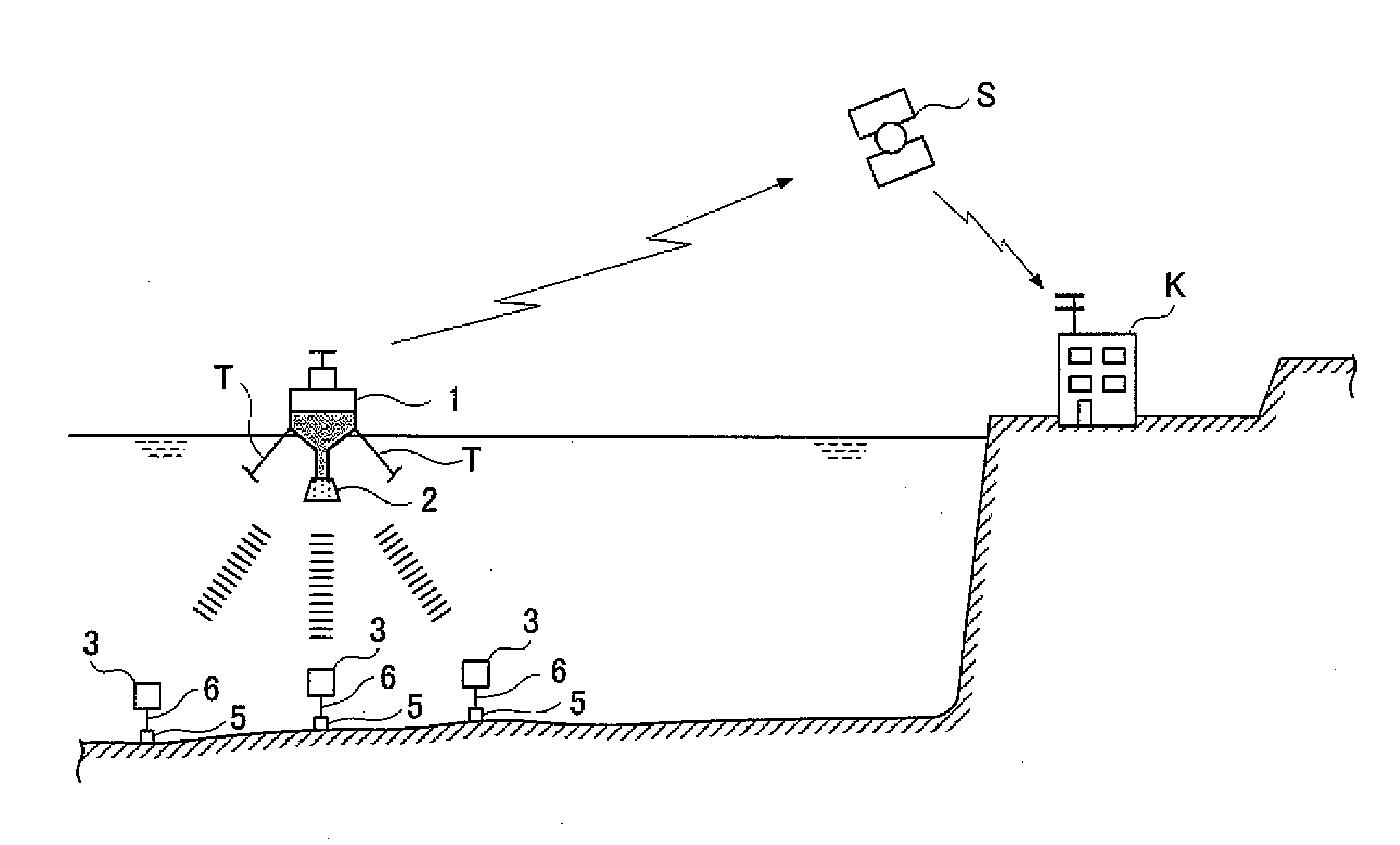
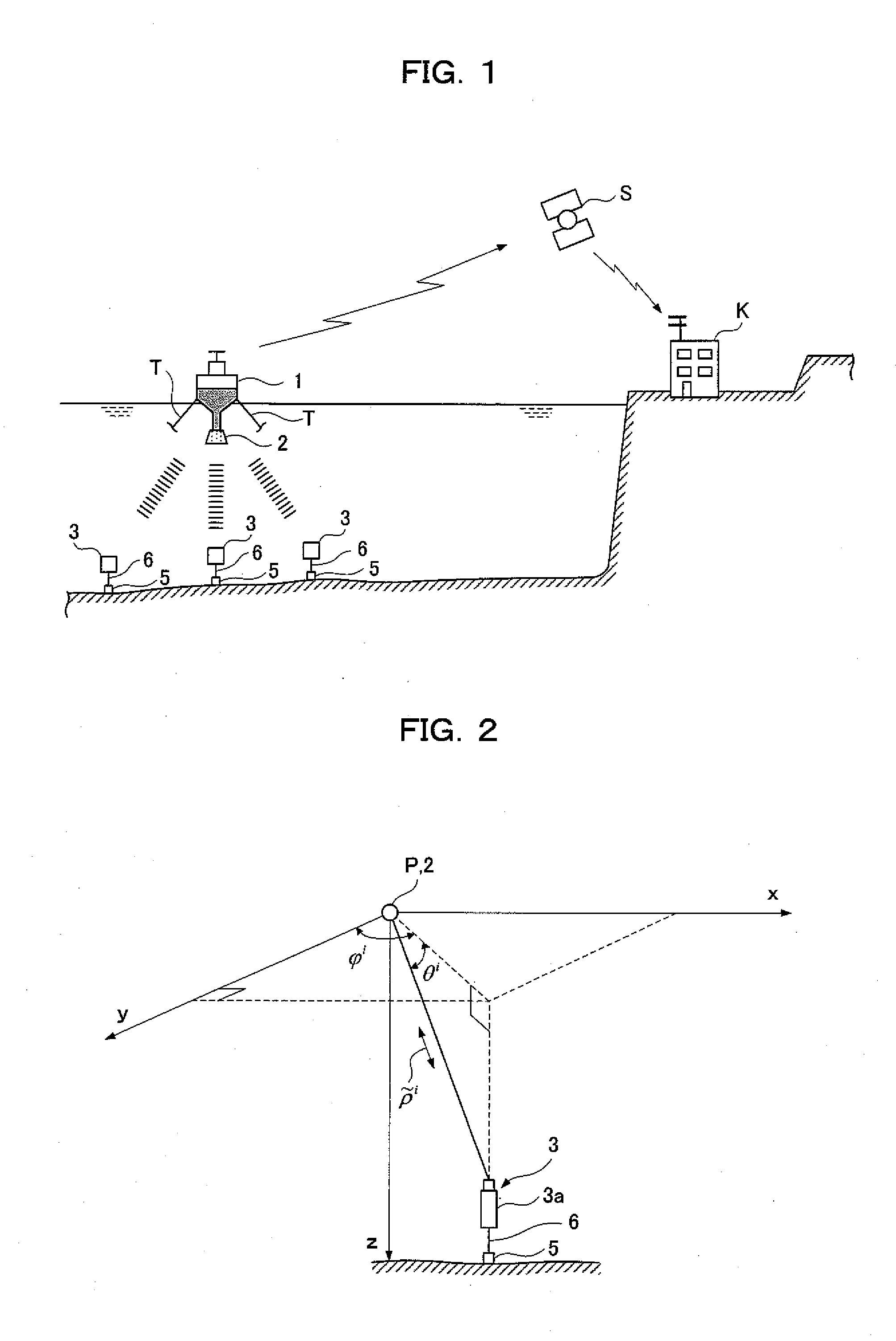
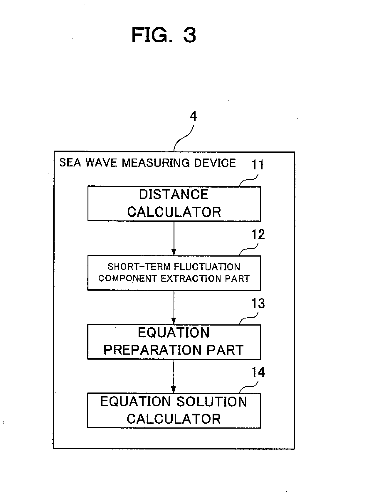
[0029]The sea wave measuring system, as shown in FIGS. 1 to 3, includes: a buoy 1 which is moored by mooring cables T, floats on the sea surface in very deep waters, and is provided with an ultrasonic receiver 2 capable of receiving ultrasonic waves; at least three ultrasonic transmitters 3 which are placed in the vicinity of the seabed substantially directly below the buoy 1 to emit ultrasonic waves toward the sea surface; and a sea wave measuring device 4 for measuring wave heights by receiving the ultrasonic waves emitted from the ultrasonic transmitters 3 with the ultrasonic receiver 2 to detect the three-dimensional position of t...

second embodiment

[0057]The following will describe a method for measuring sea waves using ultrasonic waves and a sea wave measuring system according to a second embodiment of the present invention.

[0058]In the first embodiment, ultrasonic waves emitted from the ultrasonic transmitters on the seabed are received by the ultrasonic receiver of the buoy to detect the one-way propagation time of the ultrasonic waves. In the second embodiment, however, ultrasonic waves emitted from the ultrasonic transmitter / receiver of a buoy are received and transmitted, that is, relayed by a transponder (sound wave relay device) on the seabed to detect the round-trip propagation time of the ultrasonic waves.

[0059]Similarly to the first embodiment, the second embodiment will be described from the beginning.

[0060]The sea wave measuring system, as shown in FIGS. 4 to 6, includes: a buoy 21 which is moored by mooring cables T, floats on the sea surface in very deep waters, and is provided with an ultrasonic transmitter / rec...

third embodiment

[0088]The following will describe a method for measuring sea waves using ultrasonic waves and a sea wave measuring system according to a third embodiment of the present invention.

[0089]In the second embodiment, ultrasonic waves emitted from the ultrasonic transmitter / receiver of the buoy which is provided below the sea surface are received and emitted, that is, relayed by the transponder (sound wave relay device) placed in the vicinity of the seabed to detect the round-trip propagation time of the relayed ultrasonic waves. In the third embodiment, however, the one-way propagation time of ultrasonic waves relayed by a transponder is detected.

[0090]Similarly to the second embodiment, the third embodiment will be also described from the beginning.

[0091]The sea wave measuring system, as shown in FIGS. 7 to 9, includes: a buoy 41 which is moored by mooring cables T, floats on the sea surface in very deep waters, and is provided with an ultrasonic transmitter / receiver 42 capable of transm...


PUM


Abstract

A method for measuring sea waves includes: transmitting ultrasonic waves from an ultrasonic transmitter 2 provided on a buoy 1 into the sea, and receiving the ultrasonic waves from three transponders 3 on the seabed together with the time signals; detecting distances between the transponders 3 and the ultrasonic transmitter 2 based on the propagation time of the ultrasonic waves; high-pass filtering the distance data to extract a short-term fluctuation component; preparing and solving linear equations to determine the displacement in the height direction of the short-term fluctuation component and obtain a wave height.

Description

TECHNICAL FIELD[0001]The present invention relates to a method for measuring sea waves by means of ultrasonic waves and a sea wave measuring system.BACKGROUND ART[0002]In the steady observation, that is, measurement of sea waves, an under-water pressure type wave meter has been generally used for measuring pressure fluctuations at the seabed.[0003]The under-water pressure type wave meter can be used in shallow waters but has a limited use in very deep waters with a lower sensitivity to short-period waves since the movement of water particles due to sea surface waves does not reach the seabed.[0004]Thus, when the under-water pressure type wave meter is used, observed waveforms are obtained through a low-pass filter, inevitably reducing the accuracy and reliability of observation data.[0005]Meanwhile, an ultrasonic wave meter can directly obtain waveforms on the sea surface as compared to the under-water pressure type wave meter, and has been widely used on the coasts all over the cou...

Claims


Application Information

Patent Timeline
Patent Type & Authority Applications(United States)
IPC IPC(8): G01S5/30G01C13/00
CPCG01C13/004G01S5/0009G01S5/30G01C13/002G01S15/74G01S15/874G01S15/88G01S7/003G01S15/8913
Inventor KATO, TERUYUKITERADA, YUKIHIROMIYAKE, TOSHIHIDEYOSHIDA, HARUHIKO
Owner HITACHI ZOSEN CORP
Why Eureka
Try Eureka