Proximity sensor used by an operation robot and method of operating the proximity sensor

Active Publication Date: 2012-06-14
SAMSUNG ELECTRONICS CO LTD
10 Cites 2 Cited by

AI-Extracted Technical Summary

Problems solved by technology

However, since the visual field of the camera is limited and the camera does not readily move, instruments of the operation r...

Benefits of technology

[0015]According to example embodiments, it is possible to prevent a collision between instruments of an operation robot or an unnecessary contact with a human or animal body by measuring a proximity distance between an instrument of the operation robot and the human or animal body using an ultrasonic signal generated at a piezoelectric polymer film.
[0016]According to example embodiments, it is possible to readily measure a proximity distance between a proximity sen...

Abstract

Described is a proximity sensor used by an operation robot that may measure a proximity distance to an object using an ultrasonic wave in a device such as an operation robot, an endoscope, and the like, and a method of operating the proximity sensor which may be used by an operation robot. The proximity sensor used by the operation robot may include an inner wall provided in a circular structure to secure a cavity within the circular structure, a piezoelectric polymer film disposed outside the inner wall to generate an ultrasonic signal, and to sense the ultrasonic signal, and an outer wall disposed outside the piezoelectric polymer film to propagate the ultrasonic signal via an open window, thereby preventing a collision between devices or an unnecessary contact, and providing a more stable operation environment.

Application Domain

Technology Topic

Image

  • Proximity sensor used by an operation robot and method of operating the proximity sensor
  • Proximity sensor used by an operation robot and method of operating the proximity sensor
  • Proximity sensor used by an operation robot and method of operating the proximity sensor

Examples

  • Experimental program(1)

Example

[0025]Reference will now be made in detail to embodiments, examples of which are illustrated in the accompanying drawings, wherein like reference numerals refer to like elements throughout. Embodiments are described below to explain the present disclosure by referring to the figures.
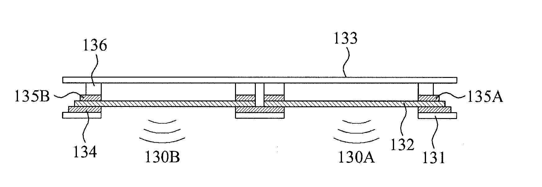
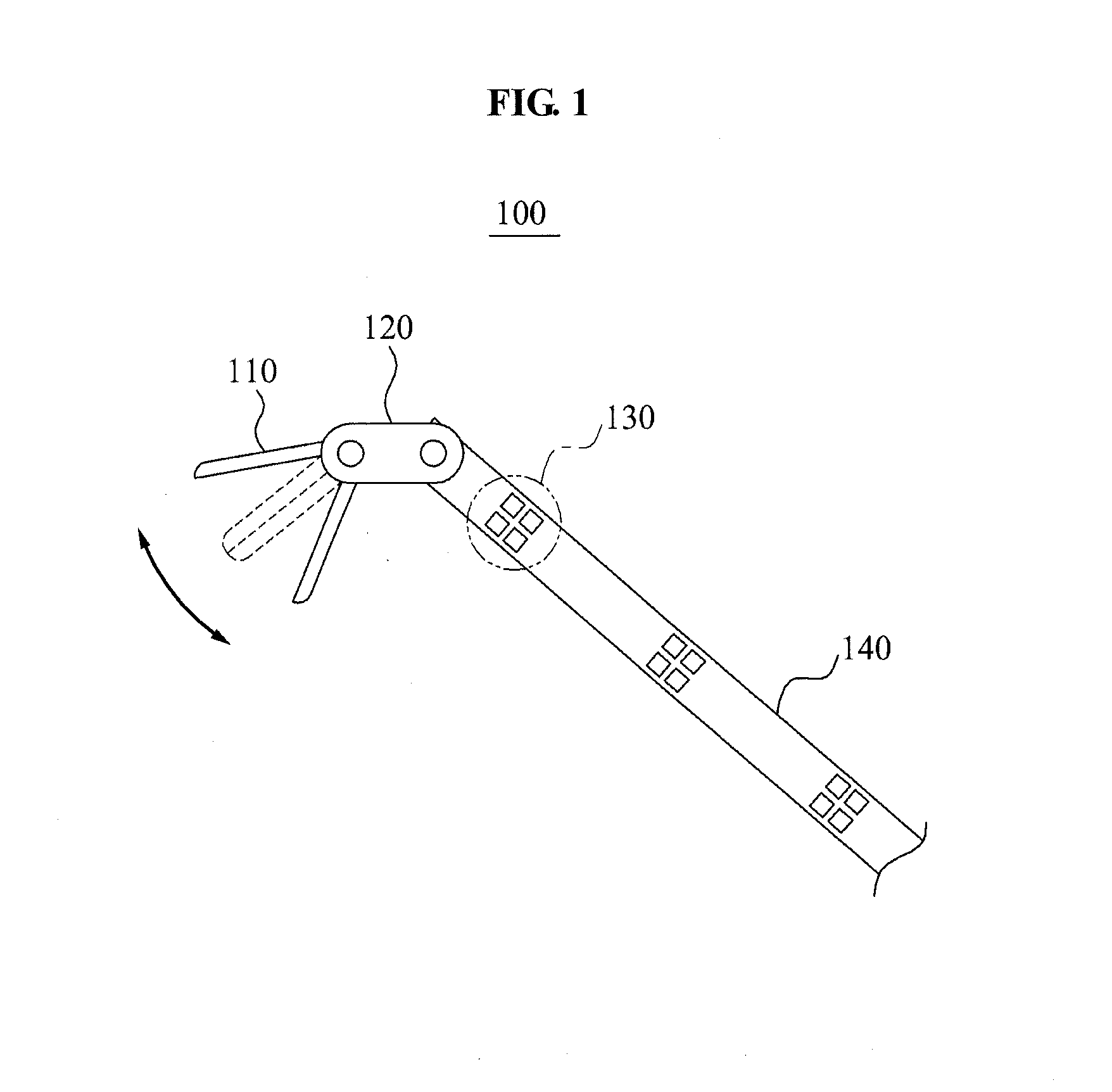
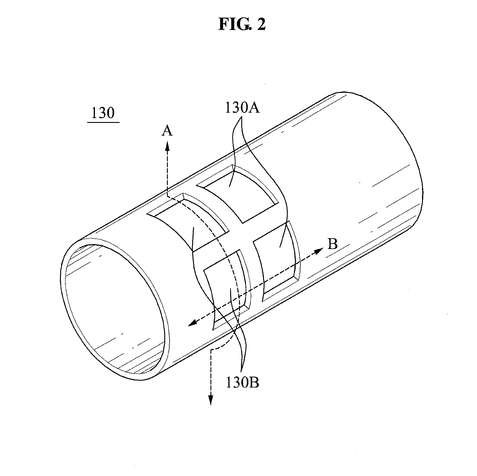
[0026]FIG. 1 illustrates a proximity sensor 130 which may be used by an operation robot applied to an instrument of the operation robot according to example embodiments.
[0027]In general, the operation robot may include a master robot and a slave robot. For example, while viewing the inside of a human or animal body displayed on a screen of the master robot, a doctor may perform an operation by manipulating an operation instrument of the slave robot via a controller.
[0028]Referring to FIG. 1, an operation instrument 100 of the slave robot is designed to move with multiple degrees of freedom (DoFs) based on an instrument 110 and a joint 120. The instrument 110 may be provided in various types of shapes depending on, for example, the intended use of the instrument. The instrument 110 and the joint 120 may be connected to the slave robot which may be placed outside a human or animal body via an extended robot arm 140. For collision prevention, a plurality of proximity sensors 130 may be installed in the robot arm 140. The proximity sensor 130 may calculate a distance between an outer wall of the robot arm 140 and another object, for example, an organ within a human or animal body, based on a time difference between a time when an ultrasonic signal occurs, and a time when the ultrasonic signal is sensed.
[0029]FIG. 2 illustrates a perspective view of the proximity sensor 130 which may be used by the operation robot of FIG. 1.
[0030]Referring to FIG. 2, the proximity sensor 130 which may be used by the operation robot may include an inner wall being provided in a circular structure to secure a cavity within the circular structure, a piezoelectric polymer film being disposed outside the inner wall to generate an ultrasonic signal, and to sense the ultrasonic signal, and an outer wall being disposed outside the piezoelectric polymer film to propagate the ultrasonic signal via an open window.
[0031]The proximity sensor 130 may further include a pillar being fixed between the inner wall and the piezoelectric polymer film to form the cavity, and to closely attach or secure the piezoelectric polymer film to the outer wall.
[0032]The piezoelectric polymer film may include a generator 130A to generate the ultrasonic signal and a receiver 130B to sense the ultrasonic signal.
[0033]FIG. 3 illustrates a cross-sectional view of the proximity sensor 130 which may be used by the operation robot cut along a direction A of FIG. 2.
[0034]Referring to FIG. 3, the proximity sensor 130 which may be used by the operation robot may include an outer wall 131, a piezoelectric polymer film 132, an inner wall 133, an external wire 134, an internal wire 135, and a pillar 136.
[0035]The inner wall 133 may be provided in a circular structure to secure a cavity within the circular structure. An inside of the circular structure may include an instrument used to perform an operation, an endoscope, and the like. The proximity sensor 130 may be formed on a ‘surface’ surrounding the instrument used to perform the operation and the endoscope. As shown in FIG. 2 and FIG. 3, the structure described is formed in a circular shape. However, it is only an example and thus, the structure may be provided in various types of shapes (e.g., elliptical, triangular, polygonal, etc.), depending on, for example, the type of operation performed or the intended use of the operation instrument.
[0036]The piezoelectric polymer film 132 may be disposed outside the inner wall 133 to generate an ultrasonic signal or to sense the ultrasonic signal. For example, when an alternating current (AC) voltage is applied to the piezoelectric polymer film 132, the piezoelectric polymer film 132 may generate the ultrasonic signal by repeating a contraction and a relaxation. When the ultrasonic signal is received at the piezoelectric polymer film 132, the piezoelectric polymer film 132 may be contracted or relaxed due to the ultrasonic signal, thereby generating an AC signal and sensing the ultrasonic signal.
[0037]Accordingly, when an AC circuit is connected to the piezoelectric polymer film 132, the piezoelectric polymer film 132 may be employed as the generator 130A to generate the ultrasonic signal. When an AC signal sensing circuit is connected to the piezoelectric polymer film 132, the piezoelectric polymer film 132 may be employed as the receiver 130B to sense the ultrasonic signal.
[0038]For example, the single piezoelectric polymer film 132 may be employed to perform as both the generator 130A and the receiver 130B. The piezoelectric polymer film 132 may be formed of, for example, polyvinylidene fluoride (PVDF).
[0039]The pillar 136 may closely attach or secure the piezoelectric polymer film 132 to the outer wall 131, and may form the cavity between the piezoelectric polymer film 132 and the inner wall 133. Accordingly, when the AC current is applied, the pillar 136 may maximize a vibration of the piezoelectric polymer film 132.
[0040]The outer wall 131 may include an open window to smoothly propagate the ultrasonic signal. A shape of the open window may define the proximity sensor 130, for example, the generator 130A and the receiver 130B. As shown in FIG. 2, the open window may be formed in a rectangular shape. However, it is only an example and thus, the open window may be provided in various types of shapes (e.g., circular, elliptical, triangular, polygonal, etc.), to maximize the generation efficiency of the ultrasonic signal.
[0041]The outer wall 131 may protect the piezoelectric polymer film 132 by coating a thin insulating layer on a portion where an external electrode of the piezoelectric polymer film 132 is externally exposed via the open window. The outer wall 131 may be formed to correspond to the pillar 136, and may efficiently propagate the ultrasonic signal to an outside by coating the insulating layer on the portion including the generator 130A and the receiver 130B of the piezoelectric polymer film 132.
[0042]FIG. 4 illustrates a cross-sectional view of the proximity sensor 130 which may be used by the operation robot cut along a direction B of FIG. 2.
[0043]Constituent elements of FIG. 4 will be the same as the constituent elements of FIG. 3.
[0044]Electrodes for applying a voltage may be coated on both sides of the piezoelectric polymer film 132. For example, the internal electrode corresponding to the inner wall 133 and the external electrode corresponding to the outer wall 131 may be coated on the piezoelectric polymer film 132. The piezoelectric polymer film 132 may receive the voltage via the internal electrode and the external electrode.
[0045]The external electrode may be in direct contact with the external wire 134. For example, the external electrode may be connected to the generator 130A and the receiver 1308 via the external wire.
[0046]The internal electrode may be connected to the internal wire 135. The internal wire 135 may be separated into a first internal wire 135A and a second internal wire 1358. For example, the first internal wire 135A may be connected to the AC circuit, and the second internal wire 1358 may be connected to the AC signal sensing circuit.
[0047]The external wire 134 and the internal wire 135 may be connected to each other via an electric wire of an operation robot system using an empty space between the outer wall 131 and the internal wall 133.
[0048]As described above, when the AC voltage is applied to the AC circuit, the piezoelectric polymer film 132 may generate the ultrasonic signal via the open window, and the outer wall 131 may propagate the ultrasonic signal to the air. The propagated ultrasonic signal may be reflected from the surface of another robot or the human or animal body and a portion of the reflected ultrasonic signal may be sensed at the receiver 1308. The proximity sensor 130 which may be used by the operation robot may calculate a distance between the outer wall 131 of the robot arm 140 and another object based on a time difference between a time when the ultrasonic signal occurs and a time when the ultrasonic signal is sensed.
[0049]FIG. 5 illustrates a method of operating the proximity sensor 130 which may be used by the operation robot of FIG. 1 according to example embodiments.
[0050]In operation 510, the proximity sensor 130 which may be used by the operation robot may secure a cavity within a circular structure in the inner wall 133 provided in the circular structure. An inside of the circular structure may include an instrument to perform an operation, an endoscope, and the like. For example, the inner wall 133 may be formed on a ‘surface’ surrounding a portion including the instrument for the operation and the endoscope in the circular structure.
[0051]In operation 520, the proximity sensor 130 may generate an ultrasonic signal at the piezoelectric polymer film 132 disposed outside the inner wall 133, or may sense the ultrasonic signal. The piezoelectric polymer film 132 may include the generator 130A to generate the ultrasonic signal using an AC circuit and the receiver 130B to sense the ultrasonic signal using the AC signal sensing circuit.
[0052]For example, when an AC voltage is applied to the AC circuit, the piezoelectric polymer film 132 may generate the ultrasonic signal by repeating a contraction and a relaxation.
[0053]When the ultrasonic signal is received at the piezoelectric polymer film 132, the piezoelectric polymer film 132 may be contracted or relaxed due to the ultrasonic signal, thereby generating an AC signal and sensing the ultrasonic signal.
[0054]In operation 530, the proximity sensor 130 may propagate the ultrasonic signal via an open window using the outer wall 131 disposed outside the piezoelectric polymer film 132.
[0055]To effectively transfer the ultrasonic signal, the outer wall 131 may propagate the ultrasonic signal via the open window. The outer wall 131 may protect the piezoelectric polymer film 132 by coating the open window with an insulating layer.
[0056]The pillar 136 may be fixed to form a cavity between the inner wall 133 and the piezoelectric polymer film 132, and may closely attach or secure the piezoelectric polymer film 132 to the outer wall 131.
[0057]According to an embodiment, the piezoelectric polymer film 132 may be coated with electrodes, for example, an internal electrode and an external electrode to apply a voltage to both surfaces. For example, the piezoelectric polymer film 132 may be coated with the internal electrode corresponding to the inner wall 133 and the external electrode corresponding to the outer wall 131. The external electrode may directly contact the external wire 134, and be connected to the generator 130A and the receiver 130B via the external wire. The internal electrode may be connected to the internal wire 135. The internal wire 135 may be separated into the first internal wire 135A and the second internal wire 135B. The first internal wire 135A may be connected to the AC circuit, and the second internal wire 135B may be connected to the AC signal sensing unit.
[0058]Proximity sensors which may be used by an operation robot and/or controllers according to example embodiments may be embodied using various types of packages. For example, the proximity sensors and/or controllers may be embodied using packages such as Package on Packages (PoPs), Ball Grid Arrays (BGAs), Chip Scale Packages (CSPs), Plastic Leaded Chip Carrier (PLCC), Plastic Dual In-Line Package (PDIP), Die in Waffle Pack, Die in Wafer Form, Chip On Board (COB), Ceramic Dual In-Line Package (CERDIP), Plastic Metric Quad Flat Pack (MQFP), Quad Flatpack (QFP), Small Outline Integrated Circuit (SOIC), Shrink Small Outline Package (SSOP), Thin Small Outline (TSOP), Thin Quad Flatpack (TQFP), System In Package (SIP), Multi Chip Package (MCP), Wafer-level Fabricated Package (WFP), Wafer-Level Processed Stack Package (WSP), and the like.
[0059]While the disclosure herein has provided example embodiments of a proximity sensor which may be used by an operation robot, for example, in a medical setting to perform an operation on a human or animal body, the disclosure is not so limited. For example, a proximity sensor used by an operation robot may be used in other settings which may benefit from the proximity sensor disclosed herein. For example, the proximity sensor may be utilized in any confined space or enclosure in which the proximity sensor may provide proximity information to a user or system, so as to avoid collisions between bodies or objects, or to prevent injuries to bodies or objects, that may be located or disposed within the space or enclosure. Possible settings may include, for example, mining operations, surveillance operations, inspection operations, repair operations, bomb disposal operations, etc., however again, the disclosure is not so limited.
[0060]Accordingly, although example embodiments have been shown and described, it would be appreciated by those skilled in the art that changes may be made in these embodiments without departing from the principles and spirit of the disclosure, the scope of which is defined by the claims and their equivalents.

PUM

no PUM

Description & Claims & Application Information

We can also present the details of the Description, Claims and Application information to help users get a comprehensive understanding of the technical details of the patent, such as background art, summary of invention, brief description of drawings, description of embodiments, and other original content. On the other hand, users can also determine the specific scope of protection of the technology through the list of claims; as well as understand the changes in the life cycle of the technology with the presentation of the patent timeline. Login to view more.

Similar technology patents

Optical pickup device

Owner:FUNAI ELECTRIC CO LTD

Side airbag device

Owner:HYUNDAI MOBIS CO LTD

Dryer lid/robot collision prevention system

InactiveUS7002134B2Prevent collisionDrying solid materials without heatInvestigating moving sheetsCollision preventionNormal position
Owner:TAIWAN SEMICON MFG CO LTD

Classification and recommendation of technical efficacy words

Why Eureka
Try Eureka