
System and method for providing improved failover performance for pseudowires

a pseudowire and failover performance technology, applied in the field of communication networks, can solve the problems of degrading network performance and insufficient failover performance of redundant pseudowires alone, and achieve the effect of improving overall failover performan

Active Publication Date: 2012-06-14
CISCO TECH INC
View PDF3 Cites 54 Cited by
  • Summary
  • Abstract
  • Description
  • Claims
  • Application Information

AI Technical Summary

Benefits of technology

The patent text discusses a method for improving the performance of pseudowires in communication networks. The technical effect of this method is to provide better failover performance in case of failure of a primary pseudowire, which is used to connect different locations in a network. The method involves specifying redundant combinations of pseudowires and assigning an active or standby status to each one based on the failure scenario. This way, data can be transferred along the backup pseudowire in case of failure. Overall, the method helps to improve the reliability and performance of pseudowire emulation edge-to-edge connections in networks.

Problems solved by technology

Since the failure of pseudowires obviously degrades network performance, some effort has been directed towards adding system redundancies including redundant pseudowires.
However, the presence of redundant pseudowires alone is insufficient to improve overall failover performance, that is, the ability to switch over automatically to a redundant or backup system.

Method used


Image

  • System and method for providing improved failover performance for pseudowires
  • System and method for providing improved failover performance for pseudowires
  • System and method for providing improved failover performance for pseudowires

Examples


example method embodiment

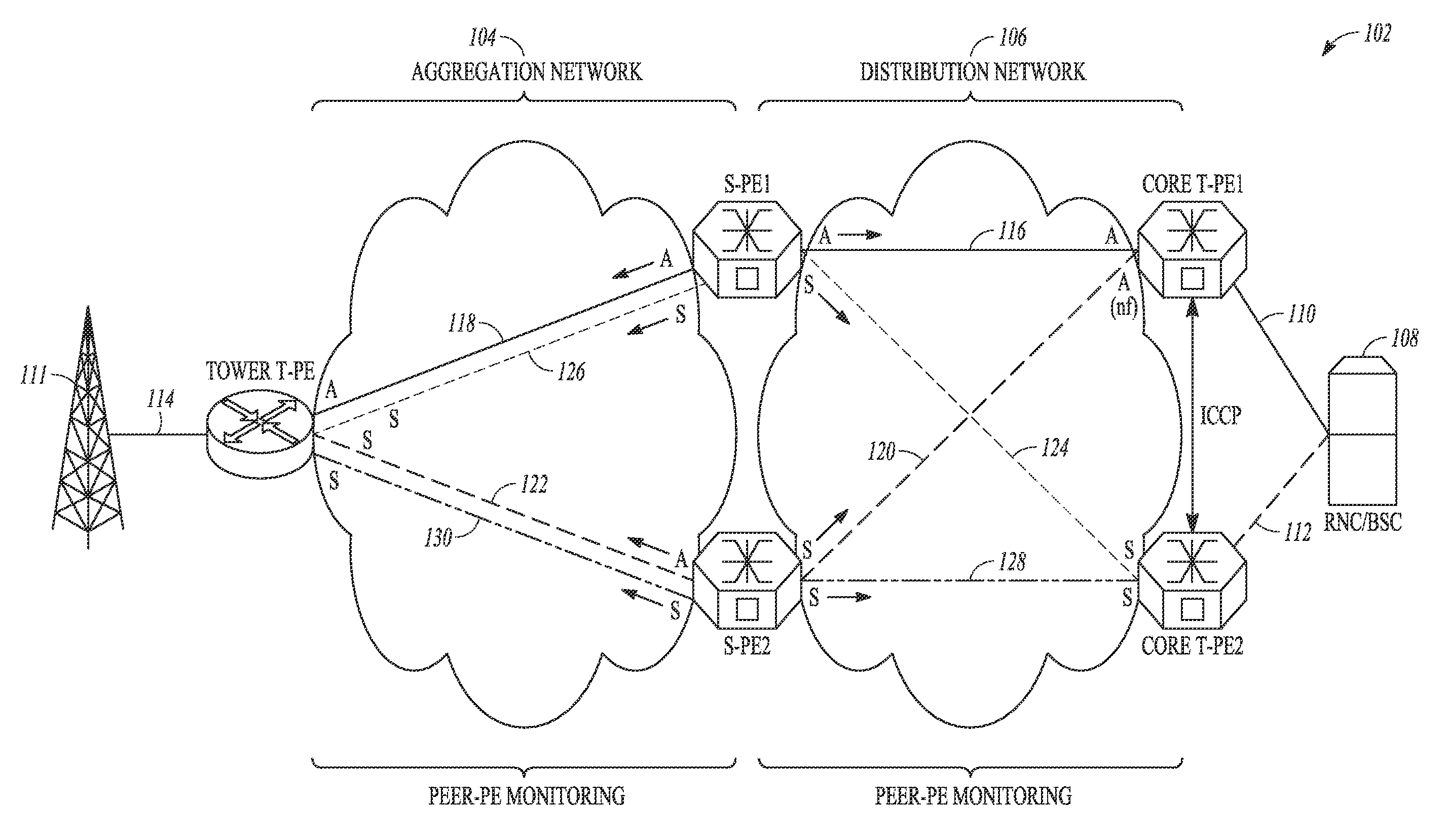
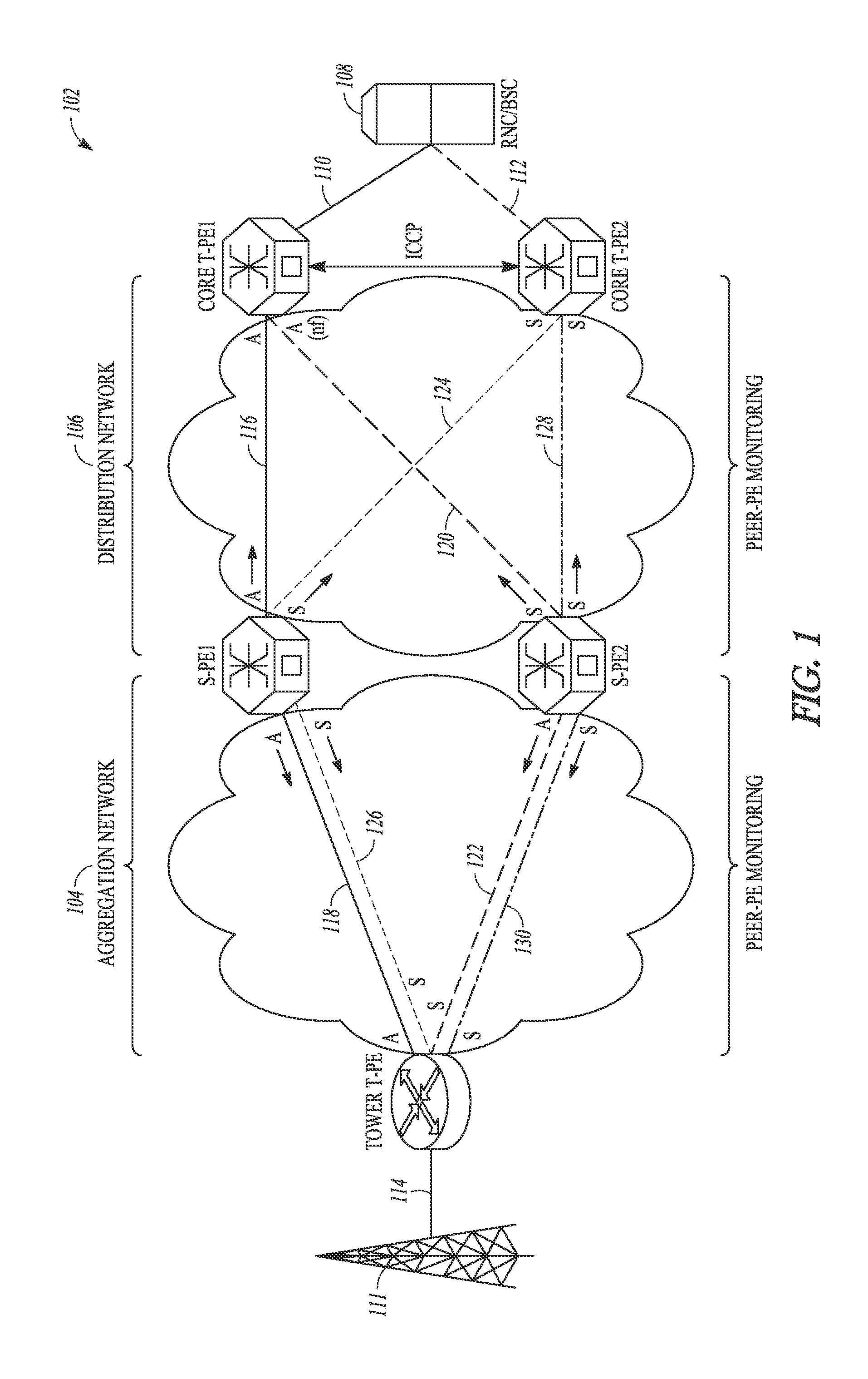
[0046]With reference to the above discussion, FIG. 10 shows a method 1002 of providing improved PW grouping according to an example embodiment. In a first operation 1004 of the method 1002, a physical interface is specified at a first PE node in a network. In a second operation 1006, a first control path is specified from the first PE node to a second PE node in the network. In a third operation 1008, a second control path is specified from the first PE node to a third PE node in the network. These control paths related to a common physical interface can be used to characterize redundant pairs of pseudowires.

[0047]In a fourth operation 1010, redundant combinations of pseudowires are specified, where each redundant combination includes a primary pseudowire that is configured as a virtual circuit between the physical interface of the first PE node and the second PE node and a backup pseudowire that is configured as a virtual circuit between the physical interface of the first PE node ...

example modular apparatus embodiment

[0052]FIG. 11 shows a schematic representation of an apparatus 1102, in accordance with an example embodiment. For example, the apparatus 1102 may be used to implement the method 1002 of providing improved pseudowire grouping as described above with reference to FIG. 10. The apparatus 1102 is shown to include a processing system 1104 that may be implemented on a server, client, or other processing device that includes an operating system 1106 for executing software instructions.

[0053]In accordance with an example embodiment, the apparatus 1102 includes a PW management module 1108 that includes a first specification module 1110, a second specification module 1112, third specification module 1114, a fourth specification module 1116, a grouping module 1118, and an assignment module 1120. The first specification module 1110 operates to specify a physical interface at a first PE node in a network. The second specification module 1112 operates to specify a first control path from the firs...


PUM


Abstract

Grouping pseudowires based on hardware interfaces and configured control paths enables improved pseudowire failover performance. Signaling status changes (e.g., from standby to active status) is facilitated by using group IDs for the pseudowire groups, thereby enabling improved failover performance when there is disruption in the network.

Description

BACKGROUND[0001]1. Technical Field[0002]The present disclosure relates generally to communication networks and more particularly to pseudowire configurations in communication networks.[0003]2. Description of Related Art[0004]Virtual Private Network (VPN) services provide secure network connections between different locations. A company, for example, can use a VPN to provide secure connections between geographically dispersed sites that need to access the corporate network so that each customer edge (CE) end point or node can communicate directly and independently with all other CE nodes. Different types of VPNs have been classified by the network layer used to establish the connection between the customer and provider network. For example, Virtual Private LAN Service (VPLS) is an architecture that delivers a multipoint Layer 2 VPN (L2VPN) service that in all respects emulates an Ethernet Local Area Network (LAN) across a wide metropolitan geographic area. All services in a VPLS appe...

Claims


Application Information

Patent Timeline
Patent Type & Authority Applications(United States)
IPC IPC(8): H04L12/26H04L45/28
CPCH04L41/0663H04L45/28H04L41/08
Inventor TAYLOR, ADAM LAURENCEYOUSUF, MUHAMMADHOLLAND, JR., JAMES RONALD
Owner CISCO TECH INC
Learn More