Nuclear reactor internal electric control rod drive mechanism assembly

Active Publication Date: 2012-06-14
WESTINGHOUSE ELECTRIC CORP
View PDF8 Cites 29 Cited by
  • Summary
  • Abstract
  • Description
  • Claims
  • Application Information

AI Technical Summary

Benefits of technology

[0016]These and other objects are achieved by a nuclear reactor power generating system having a reactor vessel including a lower section and removable upper head having a horizontal span closing off the lower section and forming a pressure vessel. A reactor core is housed in the lower section and comprises a plurality of fuel assemblies. A control rod assembly is provided, including at least one control rod that is driven into or out of a corresponding one of the plurality of fuel assemblies. A drive rod is connected to the control rod for driving the control rod into and out of the corresponding fuel assembly. A drive mechanism actuates the drive

Problems solved by technology

Inserting a control rod further into the core causes more neutrons to be absorbed without contributing to fission in an adjacent fuel rod; and retracting the control rod reduces the extent of neutron absorption and increases the rate of the nuclear reaction and the power output of the core.
In such an arrangement, the entire control rod drive mechanism is immersed within the reactor coolant, in which the conventional arrangement of coils could not operate reliably.
Even if the coils were housed to protect them from

Method used


Image

  • Nuclear reactor internal electric control rod drive mechanism assembly
  • Nuclear reactor internal electric control rod drive mechanism assembly
  • Nuclear reactor internal electric control rod drive mechanism assembly

Examples


Embodiment Construction

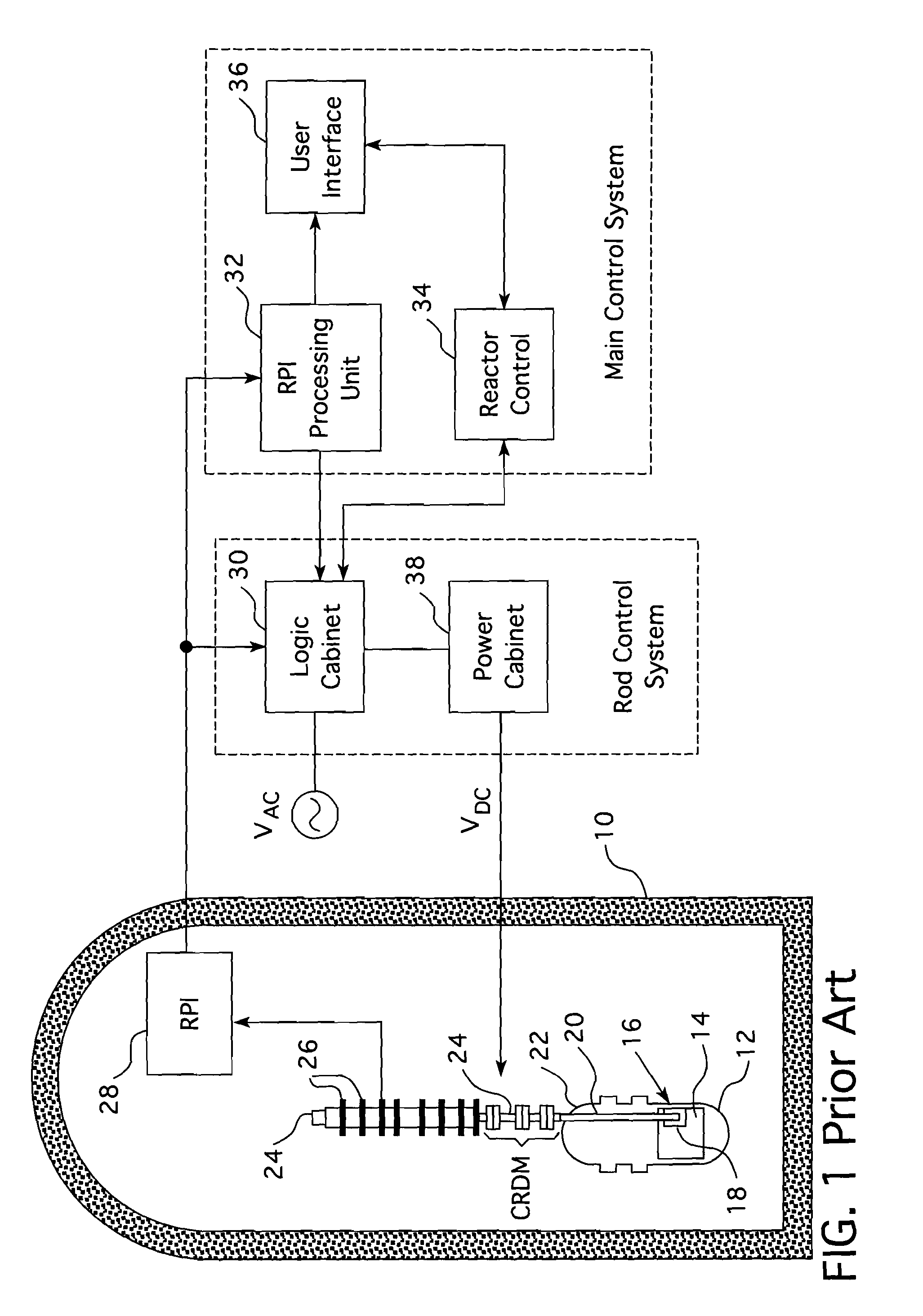
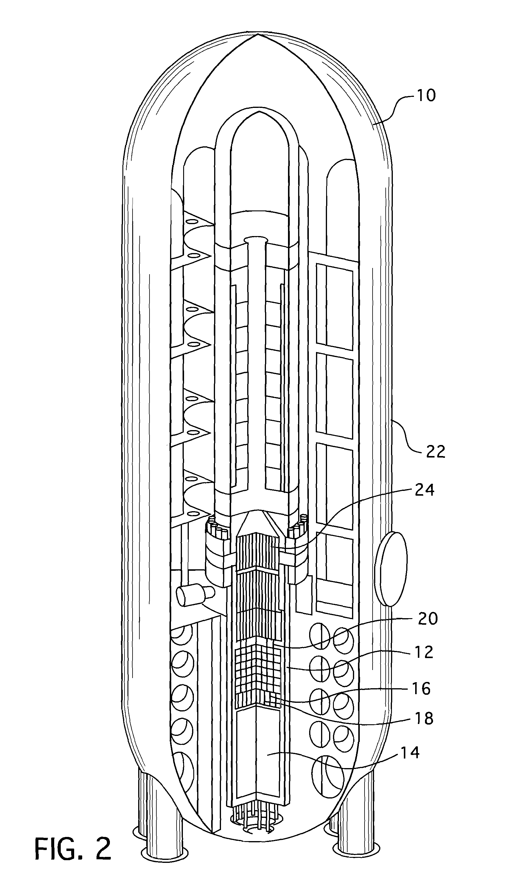
[0025]As stated in regard to FIG. 1, the control rods are attached in clusters 16, commonly referred to as spider assemblies, with each cluster being commonly driven by a drive rod 20 disposed in a vertical support housing 24 above the reactor core 14 containing the fuel assemblies into which the control rods 18 are advanced or from which the control rods are retracted for variable damping of nuclear flux within the reactor core. The moving parts of the control rod drive mechanism are within the pressure envelope of the reactor and in the conventional designs, the electromagnetic coils (CRDM) for driving the moveable parts are disposed around and about each of the housings 24 that extends above the reactor. In viewing the several figures, it should be appreciated that like reference characters refer to corresponding parts.

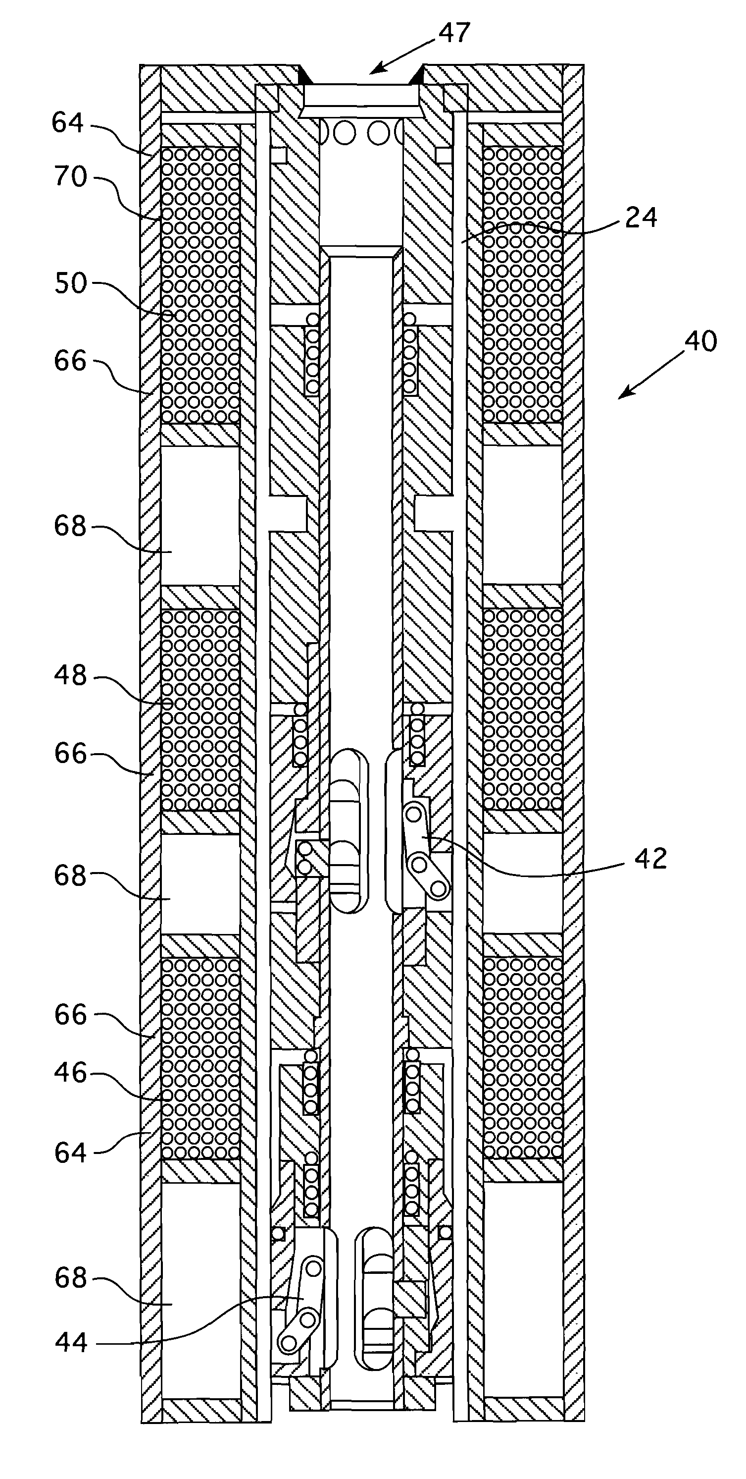
[0026]FIG. 4 shows a drive rod drive mechanism 40 with the extended portion of the housing 24 of a traditional reactor partly cut away to show the grippers 42 and ...


PUM


Abstract

A magnetic jack control rod drive rod drive system having the magnetic coils that operate the moving parts of the drive system wound from anodized aluminum magnet wire or ceramic coated nickel clad copper and enclosed within a hermetically sealed housing that is pressurized with helium.

Description

CROSS REFERENCE TO RELATED APPLICATION[0001]This application claims priority under 35 U.S.C. §119(e) to U.S. Provisional Patent Application Ser. No. 61 / 421,245, filed Dec. 9, 2010 entitled, INTERNAL ELECTRIC CRDM ASSEMBLY.BACKGROUND[0002]1. Field[0003]This invention relates in general to nuclear reactor control systems, and, in particular to systems for controlling the movement of nuclear control rods into and out of the core of the nuclear reactor.[0004]2. Description of Related Art[0005]In a nuclear reactor for power generation, such as a pressurized water reactor, heat is generated by fission of a nuclear fuel such enriched uranium, and transferred into a coolant flowing through a reactor core. The core contains elongated nuclear fuel rods mounted in proximity with one another in a fuel assembly structure, through and over which the coolant flows. The fuel rods are spaced from one another in co-extensive parallel arrays. Some of the neutrons and other atomic particles released du...

Claims


Application Information

Patent Timeline
IPC IPC(8): G21C7/16G21C7/12G21C1/00
CPCG21C7/12Y02E30/39H02K33/00Y02E30/30G21C7/08
Inventor ALLEN, BRUCE F.FALVO, GREGORY E.COOMBS, BRIAN P.
Owner WESTINGHOUSE ELECTRIC CORP
Why Eureka
Try Eureka