Fluxgate sensor and electronic compass making use thereof

a technology of electronic compass and sensor, which is applied in the direction of magnetic measurement, instruments, surveying and navigation, etc., can solve the problems of reducing the sensitivity of these sensors, limiting the azimuth accuracy of electronic compass using these sensors to approximately 10 degrees, and reducing the size of electrode pads, reducing the number of coils wound on the excitation coil, and reducing the size

Inactive Publication Date: 2012-06-21
THE FUJIKURA CABLE WORKS LTD
View PDF2 Cites 15 Cited by
  • Summary
  • Abstract
  • Description
  • Claims
  • Application Information

AI Technical Summary

Benefits of technology

[0030]According to the present invention, by winding excitation coils around the wide end portions of a magnetic core, the number of coils wound on the excitation coil is increased, and magnetic flux generated from the excitation coils in the end portions can be applied in concentration in the center portion.
[0031]According to the present invention, because it is possible to supply current si

Problems solved by technology

However, the sensitivity of these sensors is lowered when they are miniaturized, and it becomes difficult for geomagnetic levels of approximately 0.3 Oe, such as are detected by an electronic compass, to be detected accurately, and the azimuth accuracy in electronic compasses that use these sensors is limited to approximately 10 degrees.
Moreover, a large number of components such as speakers, vibration motors, and magnets and the like that serve as magnetic field generation sources are mounted inside the devices, and the sensors are affected by the magnetic fields generated from these components.
If linearity errors are considered, then in the case of MI sensors and orthogonal fluxgate sensors, hysteresis is also output in the output voltage due to hysteresis in the magnetic core.
Because of this, linearity errors are made worse.
In order to improve linearity, a method that utilizes a negative feedback circuit may be used, however, this causes power consumption to increase and also makes the circuit more complex.
Accordingly, compared with an MI sensor or an orthogonal fluxgate sensor that are constructed with only a bias coil or a pickup coil being wound aro

Method used


Image

  • Fluxgate sensor and electronic compass making use thereof
  • Fluxgate sensor and electronic compass making use thereof
  • Fluxgate sensor and electronic compass making use thereof

Examples


first preferred embodiment

[0057]Hereinafter, a first preferred embodiment of the present invention will be described in detail with reference made to the drawings.

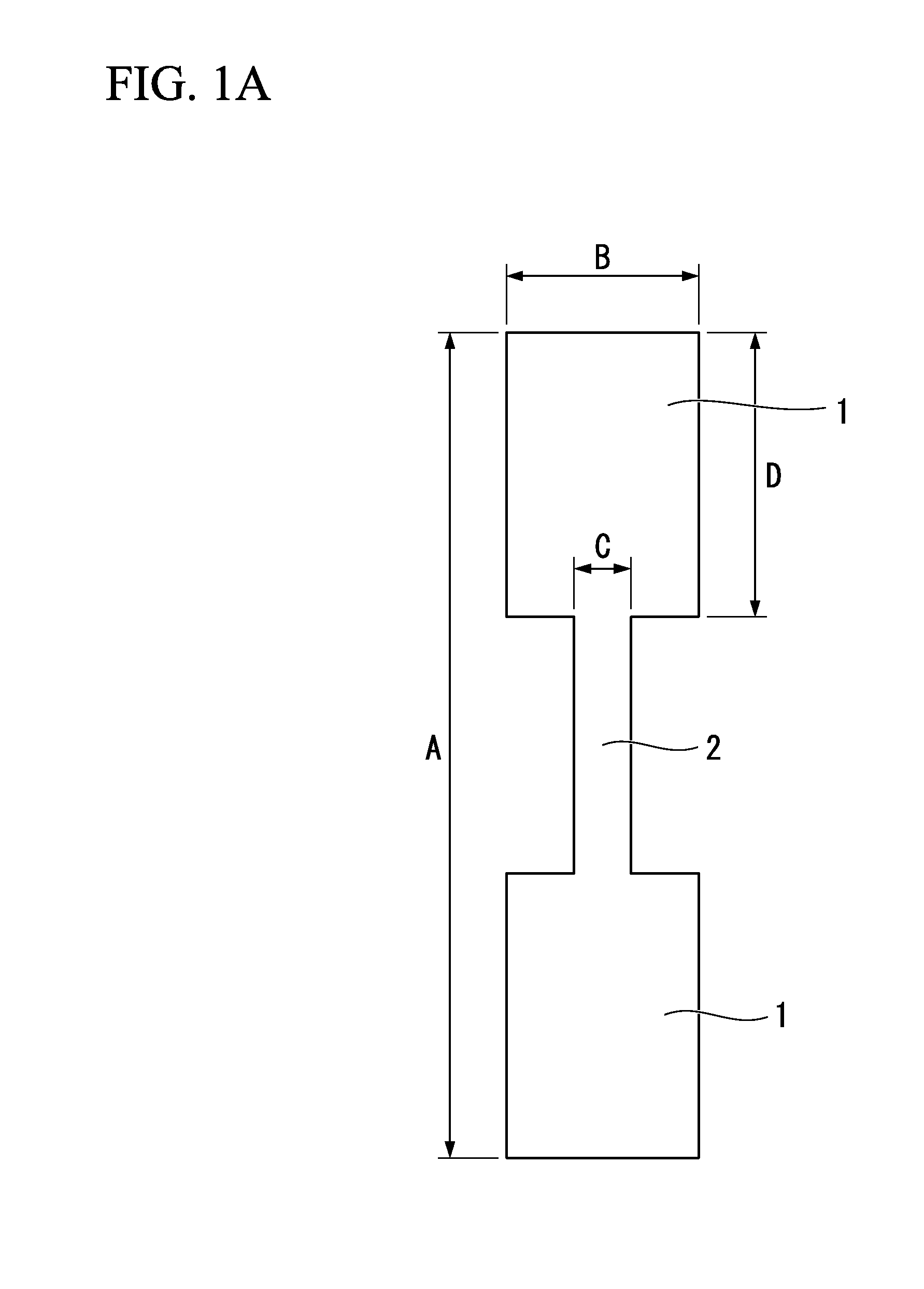
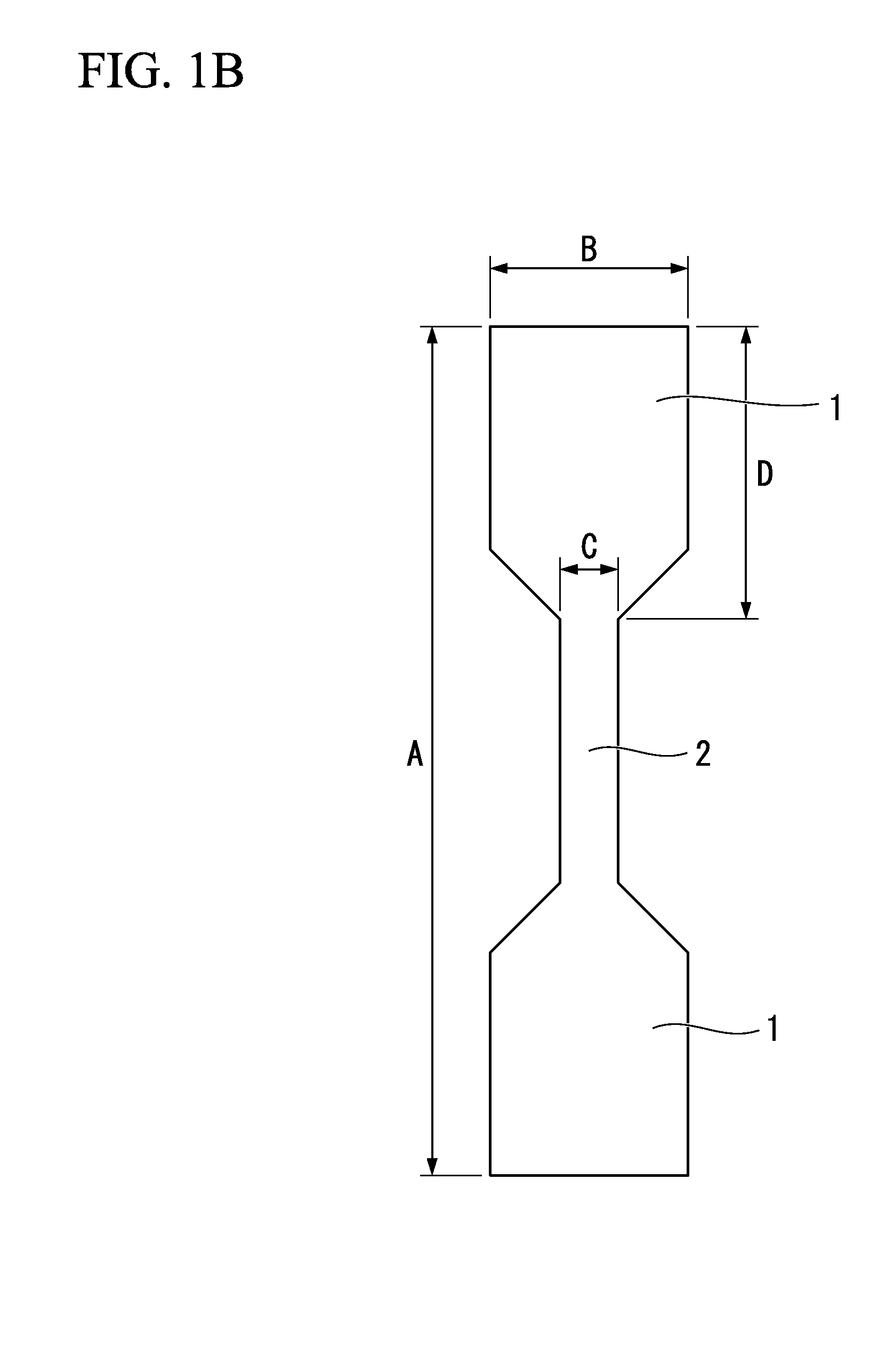
[0058]FIG. 1A and FIG. 1B are plan views showing examples of the shape of a magnetic core of a fluxgate sensor according to a first preferred embodiment of the present invention. As is shown in FIG. 1A and FIG. 1B, the magnetic core of the fluxgate sensor of the first preferred embodiment of the present invention has end portions 1 and a center portion 2. A width B of the end portions 1 is greater than a width C of the center portion 2. A length A in the longitudinal direction of the magnetic core is not more than 1 mm, and desirably not more than 0.5 mm. The value of a ratio B / D between the width B of the end portions 1 and a length D in the longitudinal direction of the end portions 1 is less than 1. The longitudinal direction of the magnetic core of the fluxgate sensor coincides with the direction of magnetic sensitivity of the fluxgate sensor. ...

examples

[0096]A fluxgate sensor was manufactured in the above described manner for use as an example. The shape of the magnetic core of the fluxgate sensor was as follows: the length A in the longitudinal direction of the magnetic core=480 μm, the width B of the end portions 1=80 μm, the width C of the center portion 2=20 μm, the length D in the longitudinal direction of the end portions 1=140 μm, the number of winds in the excitation coils was 16.5, and the number of winds in the pickup coil was 6.5.

[0097]FIG. 9 is a graph showing the output waveform of a positive / negative pulse-shaped pickup voltage when a triangular wave current having an amplitude of 100 mA, and a frequency of 30 kHz was supplied to the fluxgate sensor of the aforementioned example. FIG. 10 is a graph showing the output from a fluxgate sensor relative to the external magnetic field dependency, namely, the external magnetic field in a time interval t during which the positive / negative pulse-shaped pickup voltage shown in...

second preferred embodiment

[0112]FIG. 12 illustrates how excitation coils and a detection coil are wound in a fluxgate sensor according to a second preferred embodiment of the present invention.

[0113]In the first preferred embodiment, the excitation coils are only wound onto the broad-width end portions 1 at the two ends of the magnetic core. In contrast to this, in the second preferred embodiment, the first solenoid coils 9, which are excitation coils, are wound not only onto the broad-width end portions 1 at the two ends, but also onto the narrow-width center portion 2. Namely, the excitation coils are wound over the entire circumference of the magnetic core, and the second solenoid coil 10, which is a detection coil, is only wound onto the center portion 2 of the magnetic core. In this winding mode as well, the same operating effects as in the above described first preferred embodiment are obtained.


PUM


Abstract

Provided is a flux gate sensor comprising the following: a magnetic core having a first wiring layer formed on a board, a first insulating layer formed in such a way as to cover the aforementioned first wiring layer, and a magnetic core which is formed on the aforementioned first insulating layer and which has a central portion and an end portion that continues to the aforementioned central portion, that has a width larger than the width of the aforementioned central portion, and that is located on either side of the aforementioned central portion; a second insulating layer which covers the aforementioned magnetic core and which is formed on the aforementioned first insulating layer; and a second wiring layer formed on the aforementioned second insulating layer.

Description

CROSS REFERENCE TO RELATED APPLICATIONS[0001]This application is a continuation application based on a PCT Patent Application No. PCT / JP2010 / 003428, filed May 21, 2010, whose priority is claimed on Japanese Patent Application No. 2009-123110, filed May 21, 2009, the entire content of which are hereby incorporated by reference.BACKGROUND OF THE INVENTION[0002]1. Field of the Invention[0003]The present invention relates to a miniature fluxgate sensor that is manufactured via a thin-film process, and to an electronic compass in which this fluxgate sensor is used. In particular, the present invention relates to a fluxgate sensor that not only is small in size and is highly sensitive, but also has a high level of excitation efficiency and a high degree of design freedom, and to an electronic compass in which this fluxgate sensor is used.[0004]2. Description of the Related Art[0005]Conventional magnetic sensors include those that utilize the Hall effect, those that utilize a magnetoresist...

Claims


Application Information

Patent Timeline
IPC IPC(8): G01C17/28G01R33/04
CPCG01C17/30G01R33/05G01R33/04
Inventor OHMORI, KENICHIAIZAWA, TAKUYANAKAO, OSAMU
Owner THE FUJIKURA CABLE WORKS LTD
Why Eureka
Try Eureka