Process for the automatic control of a respirator

Inactive Publication Date: 2012-06-21
DRAGERWERK AG
View PDF2 Cites 7 Cited by
  • Summary
  • Abstract
  • Description
  • Claims
  • Application Information

AI Technical Summary

Benefits of technology

[0011]An object of the present invention is to provide a process for the automatic control of a respirator, which keeps the effects of incorrectly induced changeovers into the next phase of respiration, i.e., from inspiration into expiration or from expiration into inspiration as low as possible.
[0013]Consequently, the effects of an incorrectly triggered changeover are considerably reduced since a full inspiration or full expiration will not incorrectly pass through, if a changeover has incorrectly been triggered by an interference. If the effects of incorrect changeovers are considerably reduced in this respect by the process according to the present invention, the process according to the present invention also makes it possible to preset the threshold criteria as more sensitive, since a certain increase in incorrectly met threshold criteria can be tolerated by interferences based on the markedly reduced effects of such incorrectly triggered changeovers.

Problems solved by technology

This procedure is no longer acceptable by today's knowledge since risks of lung damage caused by the respiration have to be dealt with.
The breathing phase detection is especially often incorrect or late in newborns and in Chronic Obstructive Pulmonary Disease (COPD) patients using conventional processes and leads to increased respiratory work until exhaustion.
In practice, however, the preprocessed EMG signal is often more susceptible to interferences than pneumatic signals (pressure or volume flow).
Such a susceptibility to interferences or volatility makes it more difficult to change over or trigger the breaths when using trigger thresholds, since too many breaths may be mistakenly triggered (so-called autotrigger) or may be triggered too late (so-called delayed or missed trigger).
Marking of the signals with interferences can be avoided by suitable filterings (e.g., by means of sliding averaging) of the signals, which would result in the major drawback of an additional signal delay for the intended use for changing over between phases of respiration, however.

Method used


Image

  • Process for the automatic control of a respirator
  • Process for the automatic control of a respirator
  • Process for the automatic control of a respirator

Examples


Embodiment Construction

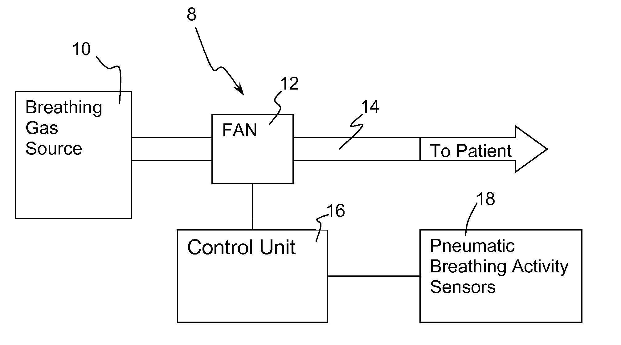
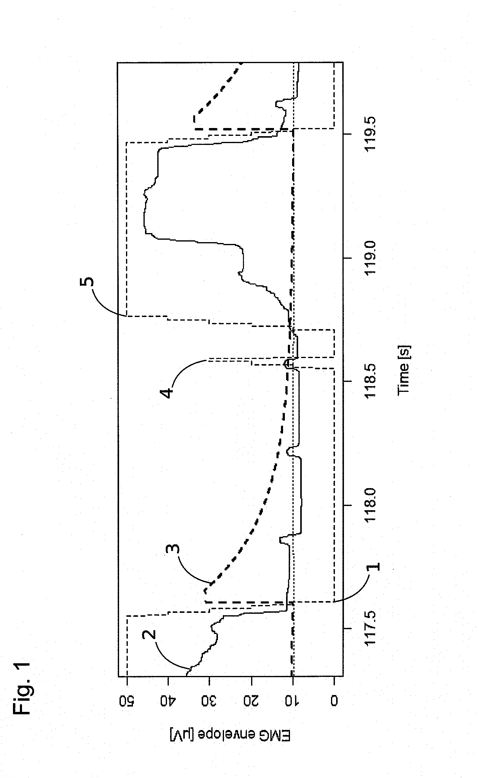
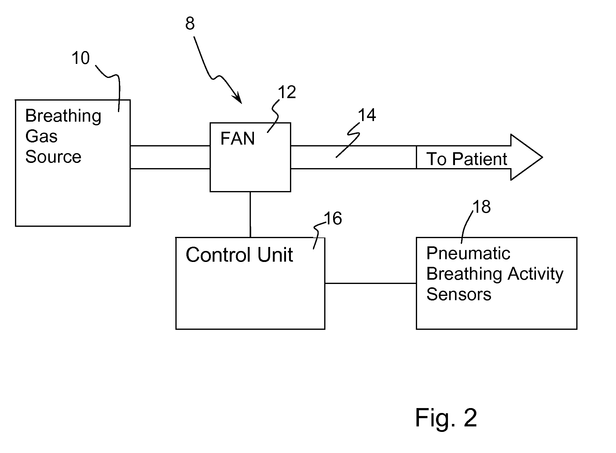
[0020]Referring to the drawings in particular, the present invention is described below based on an example in the figures, in which FIG. 1 shows the curve of the breathing activity signal, the curve of a threshold criterion and the curve of the guiding of the respiration variable by the respirator as functions of time. FIG. 2 shows a respirator 8 with a breathing gas source 10 connected to a fan 12 for conveying breathing gas through connection lines 14 to a patient. A control unit 16 controls the fan 12. Sensors 18 are connected to the control unit 16 for picking up at least one pneumatic breathing activity signal. The sensors 18 are connected to the control unit 16. The control unit controls the respirator for a consecutively made changeover between inspiration and expiration phases of respiration including controlling the fan of the respirator when changing over into a new phase of respiration, such that a pneumatic respiration variable is brought from an actual value to a prese...


PUM


Abstract

A process for the automatic control of a respirator with a changeover between phases of respiration (inspiration and expiration), by a control unit checking a breathing activity signal for a threshold criterion. If the threshold criterion is met, a changeover is made and the control unit controls the fan of the respirator such that a pneumatic respiration variable (airway pressure, flow) is brought from an actual value to a preset target value for the new phase of respiration. The control unit further divides the change in the respiration variable, from the actual value to the target value, into a plurality of partial steps and checks the current breathing activity signal for the threshold criterion after each partial step. If this threshold criterion is no longer met, the state of operation of the respirator returns to the state before the last changeover, and otherwise, continues with the next partial step.

Description

CROSS REFERENCE TO RELATED APPLICATIONS[0001]This application claims the benefit of priority under 35 U.S.C. §119 of German Patent Application DE 10 2010 055 242.9 filed Dec. 20, 2010, the entire contents of which are incorporated herein by reference.FIELD OF THE INVENTION[0002]The present invention pertains to a process for the automatic control of a respirator (also known as a ventilator), in which a changeover is consecutively made between two phases of respiration (inspiration and expiration) from one into the other, by a control unit checking a picked-up breathing activity signal in a phase of respiration for a threshold criterion for changing over into the next phase of respiration, and if the threshold criterion is met, a changeover is made from one phase of respiration into the other, whereby the control unit is further set up to control the fan of the respirator when changing over into the new phase of respiration, such that a pneumatic respiration variable (airway pressure...

Claims


Application Information

Patent Timeline
IPC IPC(8): A61M16/00
CPCA61M16/00A61M2016/0015A61M2230/40A61M2230/10A61M2230/005A61M16/024
Inventor EGER, MARCUSHANSMANN, HANS-ULLRICHGLAW, TOBIASSATTLER, FRANK
Owner DRAGERWERK AG
Why Eureka
Try Eureka