Tension rod mechanism with opposing threads

a tension rod and thread technology, applied in the direction of rod connections, couplings, curtain suspension devices, etc., can solve the problems of difficult compression of springs, scuffing or damage of support surfaces, time-consuming and exhausting constant rotation, etc., and achieve the effect of increasing the axial distan

Active Publication Date: 2012-06-21
DECOLIN INC
View PDF7 Cites 57 Cited by
  • Summary
  • Abstract
  • Description
  • Claims
  • Application Information

AI Technical Summary

Benefits of technology

[0007]Briefly stated, one embodiment of the present invention is directed to a tension rod mechanism for a tension rod having a first outer shaft and a second inner shaft slideably received by the first outer shaft and rotatable about a longitudinal axis of the tension rod. The tension rod mechanism comprises a tapered first threaded shaft having a first screw thread with a first thread direction. A first collar threadingly engages with the first threaded shaft. The first collar is configured to be received in the first outer shaft for rotational movement therewith and slidable axial movement relative thereto and to apply a outwardly-directed radial force to the first outer shaft. A second threaded shaft has a second screw thread with a second thread direction opposite the first thread direction. The second threaded shaft fixedly connected to the first threaded shaft. A second collar is threadingly engaged with the second threaded shaft and is configured to be fixedly received in the second inner shaft for movement therewith. When the first collar is in the first outer shaft and the second collar is fixedly received in the second inner shaft, a first rotation of the first outer shaft relative to the second inner shaft increases the outwardly-directed radial force applied by the first collar to the first outer shaft, and a second rotation in a direction opposite the first rotation increases the axial distance between the first and second collars.

Problems solved by technology

A user often must expand the tension rod by twenty or more inches, and the constant rotation required can be time-consuming and exhausting.
The spring can be difficult to compress, and positioning of the tension rod may scuff or damage the support surfaces as the rod is put into place.
Further, if not properly locked into place, the spring may release and cause injury to the user.

Method used


Image

  • Tension rod mechanism with opposing threads
  • Tension rod mechanism with opposing threads
  • Tension rod mechanism with opposing threads

Examples


Embodiment Construction

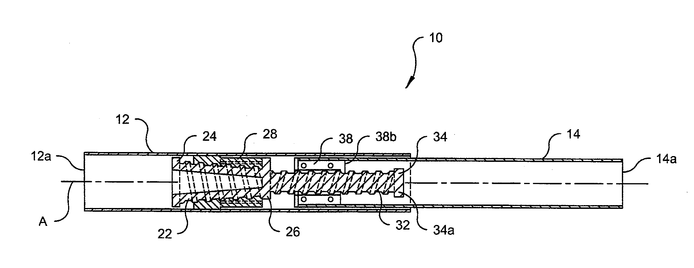
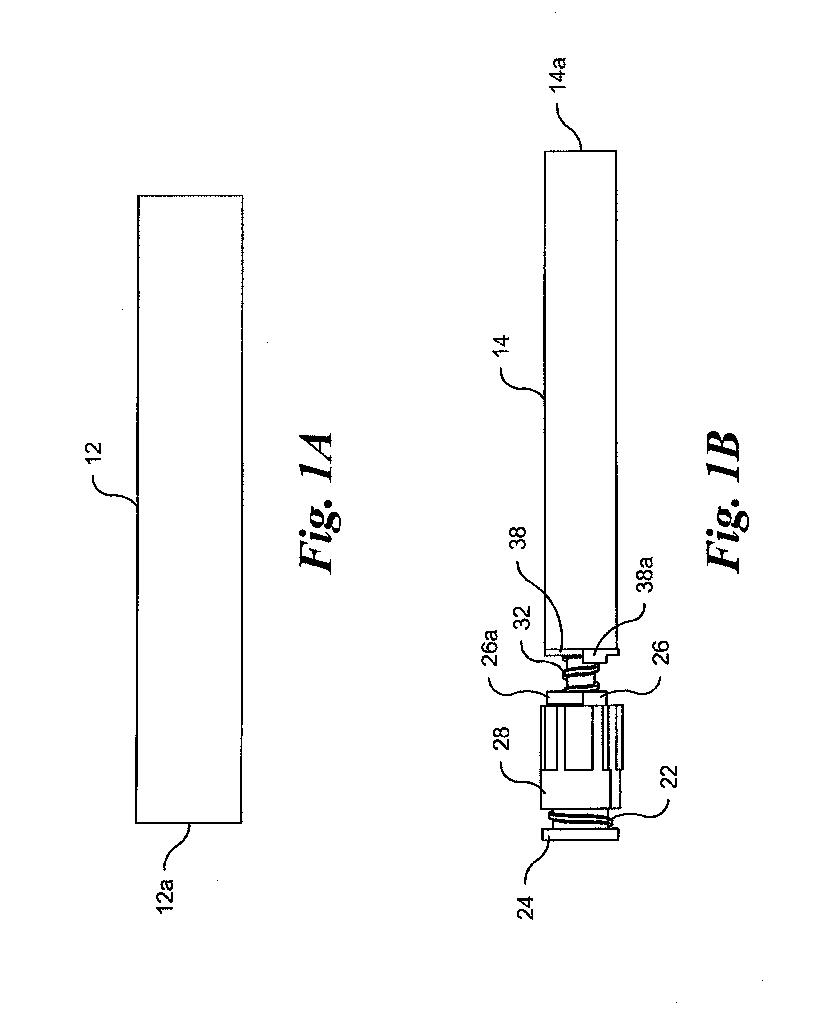
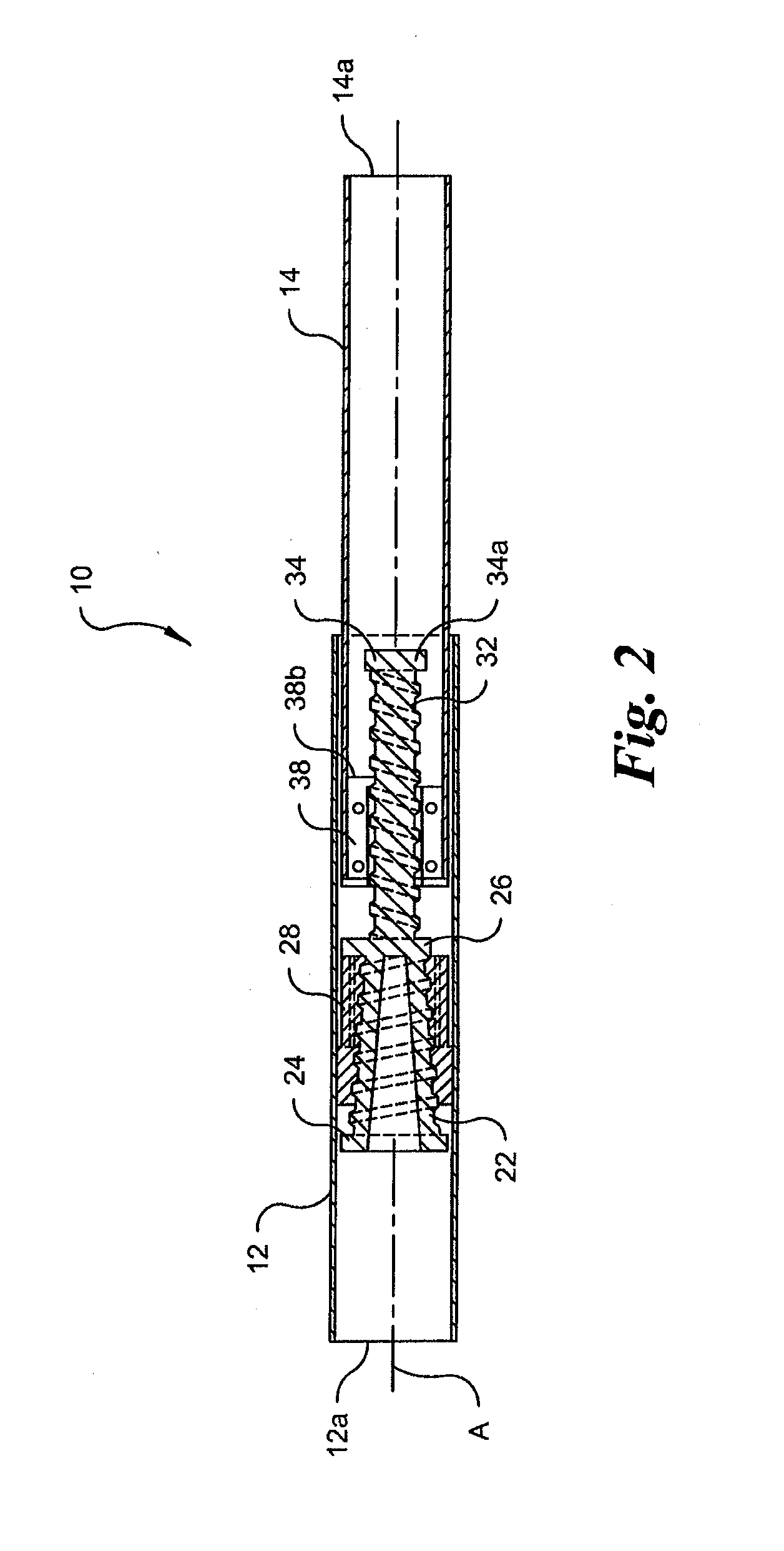
[0014]Reference will now be made in detail to embodiments of the invention, examples of which are illustrated in the accompanying drawings. The terminology used in the description of the invention herein is for the purpose of describing particular embodiments only and is not intended to be limiting of the invention.

[0015]As used in the description of the invention and the appended claims, the singular forms “a”, “an” and “the” are intended to include the plural forms as well, unless the context clearly indicates otherwise. The words “and / or” as used herein refers to and encompasses any and all possible combinations of one or more of the associated listed items. The words “comprises” and / or “comprising,” when used in this specification, specify the presence of stated features, integers, steps, operations, elements, and / or components, but do not preclude the presence or addition of one or more other features, integers, steps, operations, elements, components, and / or groups thereof.

[00...


PUM


Abstract

A tension rod mechanism for a tension rod having a first outer shaft with a second inner shaft slideable therein. A first collar receiveable in the first outer shaft of a tension rod for rotational movement therewith and slidable axial movement relative thereto threadingly engages a tapered first threaded shaft and is configured to apply a outwardly-directed radial force to the first outer shaft. A second collar fixedly receivable in the second inner shaft for movement therewith engages the second threaded shaft. A first rotation of the first outer shaft relative to the second inner shaft increases the outwardly-directed radial force applied by the first collar to the first outer shaft, and a second rotation in an opposite direction increases the axial distance between the first and second collars.

Description

CROSS-REFERENCE TO RELATED APPLICATIONS[0001]This application is related to U.S. Provisional Patent Application No. 61 / 424,458, filed Dec. 17, 2010, and claims the earlier filing dates of the provisional applications. The above-identified related application is incorporated herein by reference.BACKGROUND OF THE INVENTION[0002]The present invention relates generally to an adjustable tension rod mechanism, and more particularly, to an adjustable tension rod mechanism having opposing threads for locking the tension rod mechanism in place.[0003]Adjustable length tension rods for use as curtain or shower rods are generally used as an alternative to rods that are permanently fixed to support surfaces through the use of screws, bolts, or the like. This provides for simpler installation and prevents permanent damage to the support surfaces upon removal. These tension rods typically include a first shaft that telescopingly receives a second shaft, wherein the first and second shafts house a ...

Claims


Application Information

Patent Timeline
Patent Type & Authority Applications(United States)
IPC IPC(8): A47H1/022F16B7/18
CPCA47H1/022F16B7/06Y10T403/7054Y10T403/7058Y10T403/7069Y10T403/68Y10T403/7056
Inventor DIDEHVAR, KAVEH
Owner DECOLIN INC
Why Eureka
Try Eureka