Shaft-coupled double-period electron accelerator tube and method for frequency up-regulation of accelerator and cavity

An electron acceleration and double-cycle technology, which is applied in the direction of linear accelerators, electrical components, accelerators, etc., can solve the problems of low accelerator quality factor, shortened acceleration length, and large power loss, and achieve high microwave utilization efficiency, improved performance, and power consumption. low loss effect

Active Publication Date: 2019-05-24
中玖闪光医疗科技有限公司
View PDF6 Cites 0 Cited by
  • Summary
  • Abstract
  • Description
  • Claims
  • Application Information

AI Technical Summary

Problems solved by technology

The advantage of this method is that it increases the maximum power density of the acceleration cavity, which can fully increase the acceleration gradient and shorten the acceleration length. The disadvantage is that the quality factor of the accelerator is low and the power loss is large.
[0011] In the above two existing designs of accelerating tubes, although each has its own advantages and disadvantages, it does not give any parameters related to the cavity eigenfrequency of the accelerating cavity and the coupling cavity, that is, it does not give how to adjust the frequency of the disk-loaded waveguide. The best solution to make the eigenfrequency of the cavity can be adjusted up-frequency in the processing and debugging of the accelerating tube

Method used


Image

  • Shaft-coupled double-period electron accelerator tube and method for frequency up-regulation of accelerator and cavity
  • Shaft-coupled double-period electron accelerator tube and method for frequency up-regulation of accelerator and cavity

Examples


Embodiment Construction

[0039] The present invention will be further described in detail below in conjunction with the accompanying drawings, so that those skilled in the art can implement it with reference to the description.

[0040] It should be understood that terms such as "having", "comprising" and "including" as used herein do not entail the presence or addition of one or more other elements or combinations thereof.

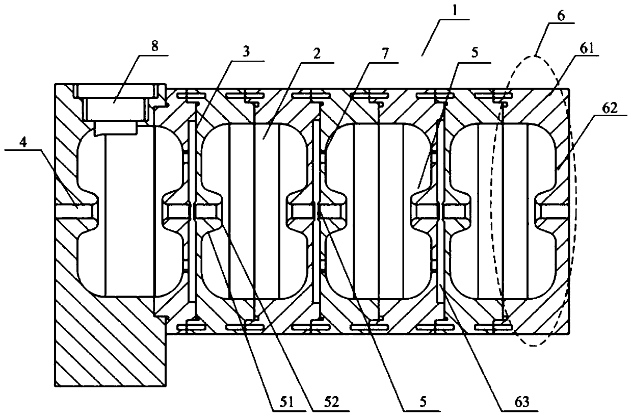
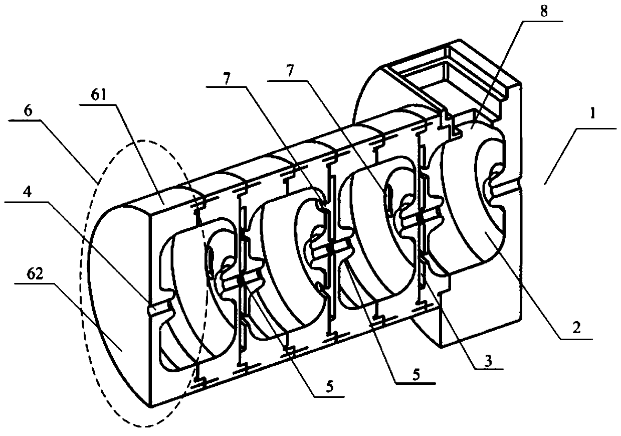
[0041] Such as figure 1 As shown, the present invention provides a shaft-coupled double-period electron accelerator tube 1, which is used to accelerate electrons in a standing wave electron linear accelerator (here figure 1 Only a part of the structure of the electron accelerating tube is shown), and there are a plurality of accelerating cavities 2 and coupling cavities 3 distributed along the axial direction and radially symmetrical with respect to the axis in the accelerating tube, and the accelerating cavities and coupling cavities are arranged alternately and On the radial s...


PUM


Abstract

The invention discloses an axis coupled double-cycle electron accelerating tube, an accelerator and a cavity ascending frequency adjusting method. A plurality of accelerating cavities and coupling cavities are alternately arranged in the accelerating tube, axially distributed and radially symmetric about an axis, mutually communicated electron beam holes are formed in radial symmetric lines, convex cone structures radially symmetric about the axis of the accelerating tube are arranged on two end faces of each of the accelerating cavities and / or the coupling cavities and positioned at the outer edges of the electron beam holes, and the axial distance between the two convex cone structures is positively correlated to the latent frequency of the corresponding cavities. The convex cone structures capable of adjusting the latent frequency of the corresponding cavities are arranged in the cavities of the axis coupled double-cycle electron accelerating tube, a new scheme is provided for adjustment of the latent frequency of the cavities, and the axis coupled double-cycle electron accelerating tube particularly has outstanding advantages for small radio-frequency accelerators.

Description

technical field [0001] The invention relates to an electron accelerating device used in nuclear technology and medical fields and a frequency adjustment method for processing and debugging the electron accelerating device. More specifically, the present invention relates to a shaft-coupled double-period electron acceleration tube, a standing wave electron linear accelerator and a cavity up-frequency adjustment method used in the nuclear technology and medical fields. Background technique [0002] An electron linear accelerator is an acceleration device that uses microwave electromagnetic fields to accelerate electrons and has a linear motion track. It is widely used in the medical field, such as common CT machines (ie, computerized tomography cameras), the most critical components of which are Electron linear accelerators use the basic principle that accelerators accelerate electrons to generate high-energy X-rays. [0003] Microwave, also known as "ultra-high frequency ele...

Claims


Application Information

Patent Timeline
Patent Type & Authority Patents(China)
IPC IPC(8): H05H7/22H05H9/04
CPCH05H7/22H05H9/04H05H2007/225
Inventor 柏伟许州杨兴繁沈旭明刘婕卢和平金晓李洪波陈门雪黎明
Owner 中玖闪光医疗科技有限公司
Why Eureka
Try Eureka