Tightening mechanism

A technology of adjusting screw and adjusting screw, applied in the direction of mechanical equipment, belt/chain/gear, transmission device, etc., can solve the problems of low efficiency, high cost and high manufacturing cost of the tensioner, and achieve strong practicability and reduce axial The effect of distance and convenient operation

Inactive Publication Date: 2011-05-11
DONGGUAN ANWELL DIGITAL MASCH CO LTD
View PDF4 Cites 0 Cited by
  • Summary
  • Abstract
  • Description
  • Claims
  • Application Information

AI Technical Summary

Problems solved by technology

The tensioning wheel type tensioning mechanism is divided into two categories: manual adjustment and automatic adjustment. The tensioning wheel type tensioning mechanism cannot rotate in reverse, and the structure of the self-adjusting tensioning wheel device is relatively complicated, and the manufacturing cost is correspondingly high; The use of manually adjusted tensioning wheels will cause low efficiency and the problem that the degree of tightness is difficult to control
Adjusting the shaft spacing type of the tightening mechanism, in which the application of the automatic type of tightening mechanism is generally driven by a motor, which has the problems of complex structure and high cost; while the manual type of adjusting the shaft spacing adjustment mechanism generally uses bolts and nuts to adjust or directly rely on experience Manual adjustment, the above-mentioned tightening method cannot guarantee the accuracy of adjustment and the size of the tension force

Method used


Image

  • Tightening mechanism
  • Tightening mechanism
  • Tightening mechanism

Examples


Embodiment Construction

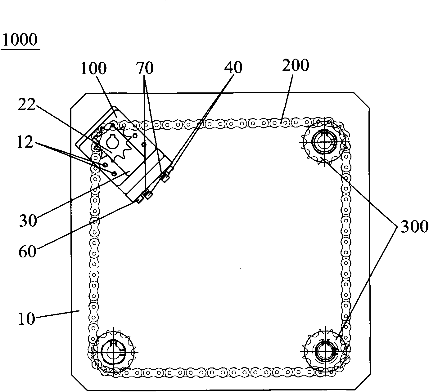
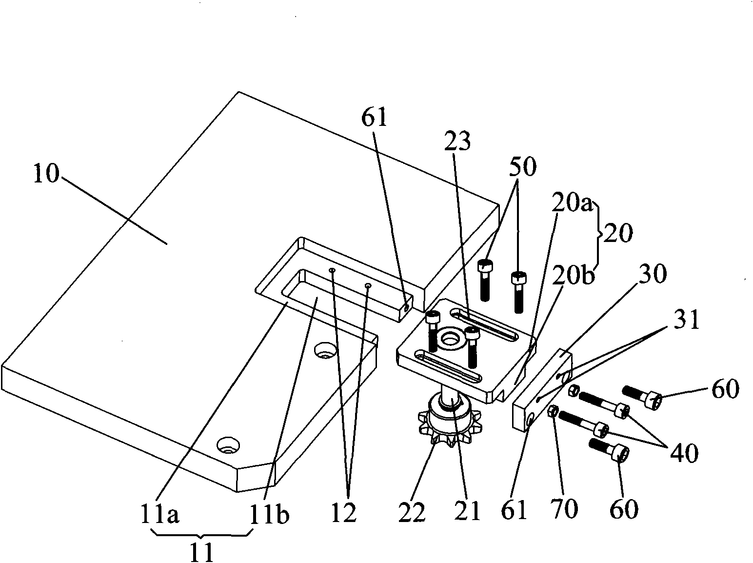
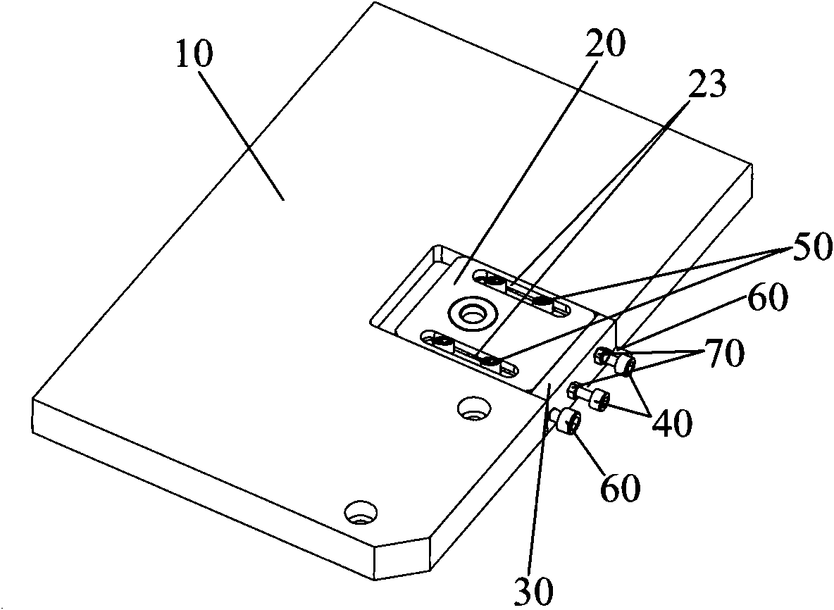
[0027] figure 1 It is a schematic diagram of the structure of the device 1000 of the first embodiment of the application of the tightening mechanism of the present invention, such as figure 1 As shown, the device 1000 includes three fixed wheels 300 , a chain 200 , and a tightening mechanism 100 . combine figure 2 , the tightening mechanism 100 includes a fixed plate 10, a slider 20, a stopper 30, an adjusting screw 40 and a positioning screw 50. In this embodiment, the number of the adjusting screw 40 and the positioning screw 50 is two . The fixing plate 10 is provided with a straight guide groove 11 , and the opening of the straight guide groove 11 is arranged on one side of the fixing plate 10 . The slider 20 is engaged and slidably connected with the straight guide groove 11, the slider 20 is equipped with a support shaft 21 protruding from the straight guide groove 11, and a tensioning wheel 22 is installed on the support shaft 21, The opening ends of the stopper 30...


PUM


Abstract

The invention discloses a tightening mechanism, comprising a fixed plate, a slide block, a stop dog and an adjusting screw. The fixed plate is provided with a straight guide slot, wherein the opening of the straight guide slot is positioned at one side of the fixed plate; the slide block is clamped and connected with the straight guide slot in sliding manner; the slide block is provided with a fulcrum shaft extended out of the straight guide slot; a tightening wheel is installed on the fulcrum shaft; the stop dog is fixedly connected with the opening of the straight guide slot and provided with a stop dog adjusting screw hole matched with the adjusting screw; and the adjusting screw passes through the stop dog adjusting screw hole to contact the slide block. The adjusting screw spirals into the stop dog to push the slide block so that the slide block linearly moves along the straight guide slot, thereby increasing the axial distance of the tightening wheel; the adjusting screw is spirally withdrawn from the stop dog, and the tightening wheel moves along the withdrawing direction of the adjusting screw under the acting force of chain or belt so as to reduce the axial distance of the tightening wheel. The mechanism has convenient operation and strong utility.

Description

technical field [0001] The invention relates to the mechanical field, in particular to a tensioning mechanism for maintaining a certain tension of a belt or chain through position adjustment. Background technique [0002] In the modern production field, the smooth progress of chain drive and belt drive requires a certain tension on the chain or belt. If the preload is too small, the ability and efficiency of load transmission will be reduced. If the preload is too large, the load on the shaft and bearing will increase, which will aggravate the wear of the bearing and reduce the life of the belt or chain. Whether the preload is too large or too small, it will affect the transmission accuracy, efficiency, and even the processing accuracy and quality of the product. It can be seen that whether the design of the tightening mechanism is reasonable and whether it is excellent is an important factor for the normal operation of the belt drive or chain drive. [0003] The current t...

Claims


Application Information

Patent Timeline
Patent Type & Authority Patents(China)
IPC IPC(8): F16H7/08
Inventor 杨明生范继良刘惠森王曼媛王勇
Owner DONGGUAN ANWELL DIGITAL MASCH CO LTD
Why Eureka
Try Eureka