Easy Open Bakeable Shipping Tray

a shipping tray and bakeable technology, applied in the field of paperboard cartons, can solve the problems of limited use of limited use of foldable trays, paperboard and corrugated paperboard cartons, etc., and achieve the effects of reducing sidewall bowing, reducing the thickness of the tray, and increasing the strength of the holder

Inactive Publication Date: 2012-06-21
INNOVATIVE FIBER
View PDF6 Cites 4 Cited by
  • Summary
  • Abstract
  • Description
  • Claims
  • Application Information

AI Technical Summary

Benefits of technology

[0011]Briefly described, one aspect of the present invention provides a tray formed from a generally flat, rectangular blank. The blank generally comprises: a bottom panel bounded by first and second end score lines and first and second side score lines; first and second end panels connected to the opposite ends of the bottom panel at the first and second end score lines; first and second side panels connected to the opposite sides of the bottom panel at the first and second side score lines; and corner webs or gussets adjacent a pair of corners of the bottom panel between a first end panel and the adjacent side panels. The tray also includes a pair of panel extensions disposed opposite the bottom panel on the longer portions of the tray, whether the longer panels are the side panels or the end panels. In the assembled portion of the tray, the extensions are folded over the side or end panels to which they are connected to form a reinforced side or end panel of the tray. This configuration of the tray with the reinforced, doubled over, longer or length panels of the tray provides the tray with added strength along the longer dimension of the tray. One advantage to the doubling over of the length panel (or whether the side or end panel) in the tray configuration of the present invention is that it creates a stronger tray with a corresponding reduction of sidewall bowing. By using the length panel folded over, the same square footage of corrugated material is used to form the tray as in a conventional tray with the width panel fold over, but the linear strength increases dramatically. This change in configuration and resulting strength increase accommodates a desire to be able cut product in the corrugated trays which cannot be accomplished with any bowing or deflection of the tray in the cutting process, or else the product will be miscut. Also, by doubling over the length panel and creating the increased strength provided by tray configuration of this disclosure, it is possible to reverse the corrugation in the tray to the short direction, conversely to prior art trays. This reduces any bottom bowing associated with prior art trays, and still functions to limit false scoring and the resulting damage to frozen product in the tray.
[0013]According to a further aspect of the present invention, when the extensions are formed on the side panels, at the opposite end of the tray formed with the second end panel, the extensions are formed with a rounded shape and a pair of tabs or locking members thereon. The tabs are selectively engaged with notches or slits in the side walls of the tray. The engagement of the tabs enables the second end panel to pivot along the end score line connecting the second end panel to the bottom panel, thereby providing an opening mechanism for accessing the contents of the tray.

Problems solved by technology

Automated construction of foldable trays has been limited primarily to the high-speed production of like trays of the same size.
The nature of paperboard and corrugated paperboard cartons, however, limits their use to post-preparation storage and handling of most food products.
For example, typical paperboard and corrugated paperboard are generally inadequate for use during the baking or cooking of food items, as the materials from which they are constructed will burn or char at elevated temperatures.
The bottom bowing of trays is a problem in the baking industry because when the trays are column stacked in a corrugated box, the icing or other product disposed in a lower tray will come in contact with a bowed bottom panel from the tray immediately above the product.

Method used


Image

  • Easy Open Bakeable Shipping Tray
  • Easy Open Bakeable Shipping Tray
  • Easy Open Bakeable Shipping Tray

Examples


Embodiment Construction

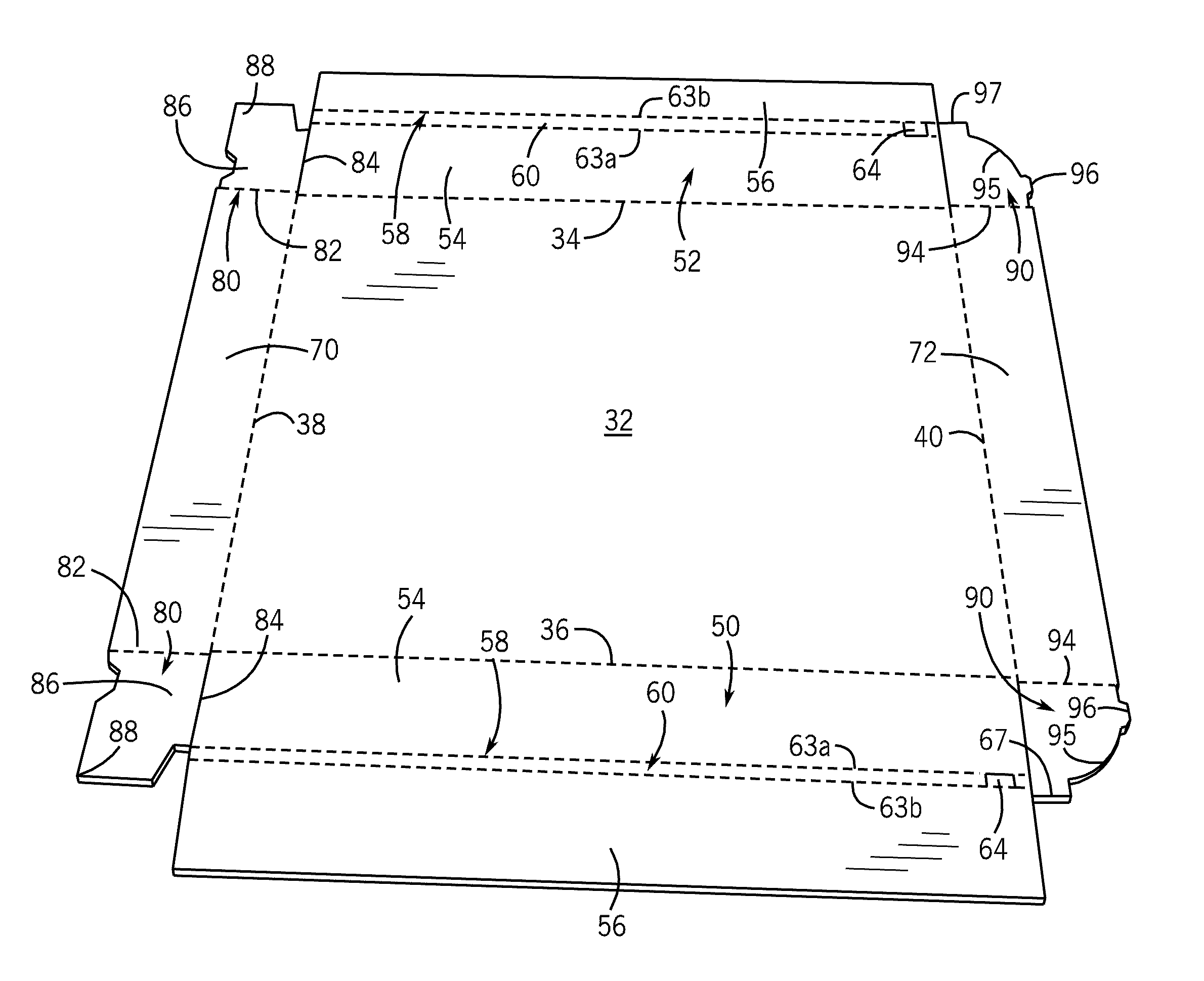
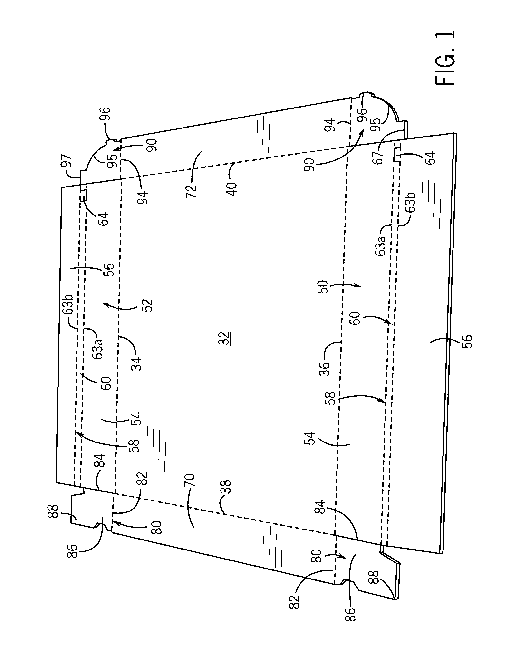
[0021]Referring now in detail to the drawing figures, wherein like reference numerals represent like parts throughout the several views, FIG. 1 shows a one-piece blank 30. The blank 30 is die cut and scored, according to known techniques, from a flat sheet of a suitable material, which in the illustrated embodiment is a heat-resistant laminated paperboard or corrugated paperboard having a laminated linerboard. The blank 30 comprises a heat-resistant laminated paperboard or corrugated paperboard, such as a corrugated paperboard known by the name E-flute, however, the blank 30 can be fabricated from any of a variety of foldable paperboard, cardboard, or other materials. In order to provide a leakproof and heat-resistant container, the material comprising the blank 30 is preferably a laminated composite including a layer of plastic film bonded to the paperboard, cardboard, or other material of construction. In one embodiment, a corrugated paperboard stock is provided with a layer of pl...


PUM


Abstract

A generally flat blank used to form an open-top container, the blank comprising a bottom panel bounded by end and side score lines, first and second side panels connected to the opposite sides of the bottom panel at the respective side score lines, each of the first and second side panels having a flap panel, each flap panel connected to each end panel by a hinged fold joint having a retaining slit, a first end panel connected to one end of the bottom panel at one score lines, a second end panel connected to the bottom panel opposite the first end panel and at least one locking extension connected to the second end panel having at least one locking member thereon that is releasably engageable with the retaining slit on the fold joint to selectively lock the second end panel with regard to the first and second side panels.

Description

CROSS-REFERENCE TO RELATED APPLICATIONS[0001]This application claims priority from U.S. Provisional Patent Application Ser. No. 61 / 423,705, filed on Dec. 16, 2010, the entirety of which is expressly incorporated herein by reference.FIELD OF THE INVENTION[0002]The present invention relates generally to a paperboard carton formed from a flat blank, and relates more specifically to a flat, die-cut blank of laminated paperboard or corrugated paperboard that can be formed into a tray, which tray can be used for baking, shipping and storing food and other products and eliminates the need for gluing or adhering, taping and the like to lock the walls of the tray in an upright configuration.BACKGROUND OF THE INVENTION[0003]Conventional foldable paperboard, cardboard or other material cartons are well known and are used worldwide in a variety of applications. For example, the packaging industry utilizes a vast number of cartons in which numerous products are packaged for subsequent shipment. ...

Claims


Application Information

Patent Timeline
Patent Type & Authority Applications(United States)
IPC IPC(8): B65D25/00B31B1/26
CPCB65D5/0015B65D25/005B65D5/22
Inventor COVELLI, JEFFREY S.
Owner INNOVATIVE FIBER
Why Eureka
Try Eureka