Position finding system

Active Publication Date: 2012-06-21
PEPPERL FUCHS GMBH
View PDF31 Cites 20 Cited by
  • Summary
  • Abstract
  • Description
  • Claims
  • Application Information

AI Technical Summary

Benefits of technology

[0009]It is therefore an object of the invention to provide a position finding system, and to provide a use of suc

Problems solved by technology

It is a disadvantage in the prior art position finding systems that the position cannot be determined immediately at any point in time, and/or the position finding systems are costly to manu

Method used


Image

  • Position finding system
  • Position finding system

Examples


Embodiment Construction

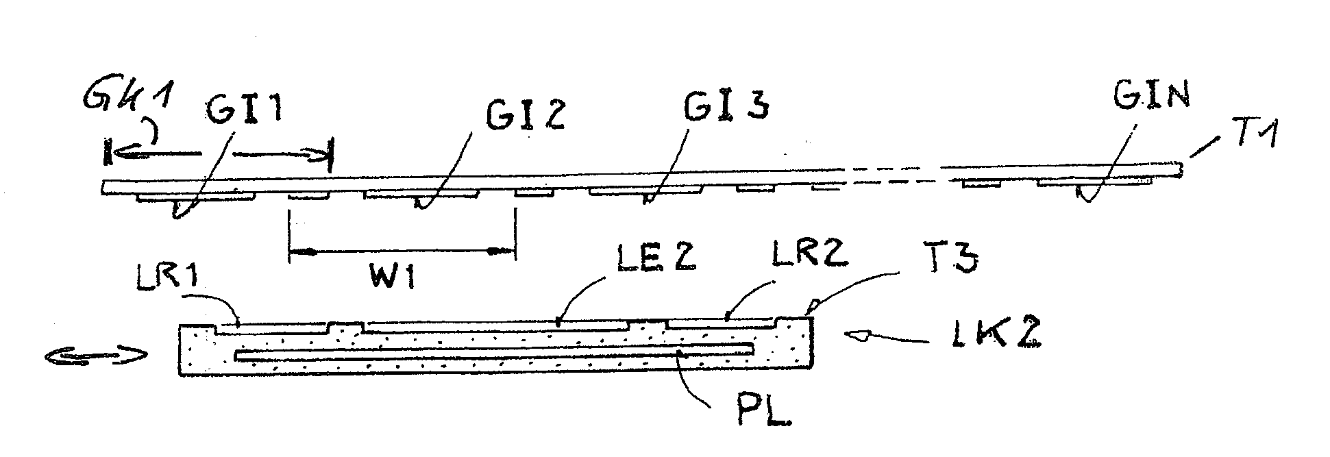
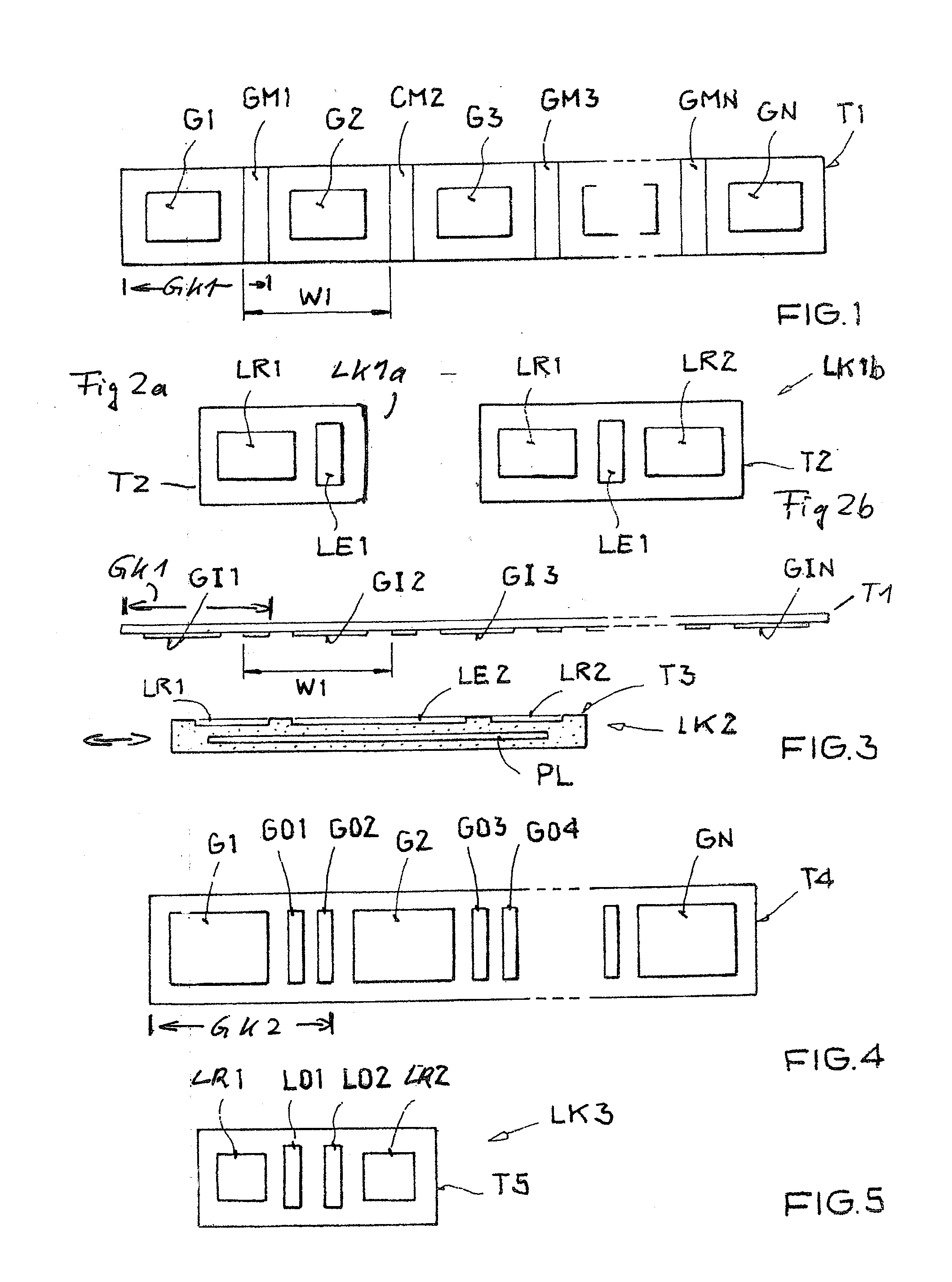
[0033]The illustration in FIG. 1 shows a top view of a first schematic embodiment of a row of transmitter units arranged on a first carrier T1. The first carrier T1 preferably is implemented as a flexible tape that preferably can be unrolled from a roll. A first transmitter unit GK1 having an RFID transponder G1 and a component transmitter unit GM1 made of a metallic material. Correspondingly, the subsequent transmitter units comprise an RFID transponder G2 and a component transmitter unit GM2 made of a metallic material or an RFID transponder G3 and a component transmitter unit GM3 made of a metallic material, and the last transmitter unit, an RFID transponder GMN-1 and a component transmitter unit GMN-1 made of a metallic material. The arrangement in a row of transmitter units, which represents an alternating arrangement of RFID transponders and the component transmitter units made of a metallic material, is terminated by an RFID transponder GN. The length of a transmitter unit is...


PUM


Abstract

Position finding system having a sensor unit and a transmitter unit. The sensor unit comprises a first RFID transponder reader unit, a first inductive detector unit, and an analysis unit connected to the RFID transponder reader unit and the inductive detector unit; the transmitter unit comprises an RFID transponder and a metallic material. The sensor unit is movable relative to the transmitter unit. The RFID transponder reader unit is configured for absolute position finding and outputs a first position value, and the inductive detector unit is configured for absolute position finding and outputs a second position value. The analysis unit is configured to determine, from the data acquired from the transmitter unit, an absolute position of the sensor unit from the first and second position values.

Description

[0001]This nonprovisional application claims priority to U.S. Provisional Application No. 61 / 423,949, which was filed on Dec. 16, 2010, and which is herein incorporated by reference.BACKGROUND OF THE INVENTION[0002]1. Field of the Invention[0003]The invention relates to a position finding system, a use of the position finding system, and a method for determining position.[0004]2. Description of the Background Art[0005]Such a system is known from DE 10 2006 004 938 A1. The position finding system described therein is used for determining the position of a vehicle, for example. RFID transponders are used by preference for this purpose. Another position finding system is known from WO 2008 / 101702, which corresponds to US 2010 / 0141244. There, the induction in a sensor from a magnet located on a wheel is sensed in order to determine the position of the wheel. Another position finding system is known from DE 10 2008 044 739 A1, which corresponds to US 2010 / 0308803, and in which the positi...

Claims


Application Information

Patent Timeline
IPC IPC(8): B61L25/02G08B5/22
CPCB61L3/125G05D1/028G05D1/0265B61L25/025
Inventor GALM, TIMOFREUND, THOMAS
Owner PEPPERL FUCHS GMBH
Why Eureka
Try Eureka