Eureka AIR delivers breakthrough ideas for toughest innovation challenges, trusted by R&D personnel around the world.

Pre-deformed thermoplastics spring and method of manufacture

Active Publication Date: 2012-06-21
ILLINOIS TOOL WORKS INC
View PDF6 Cites 6 Cited by
  • Summary
  • Abstract
  • Description
  • Claims
  • Application Information

AI Technical Summary

Benefits of technology

[0008]The pre-deformed thermoplastic spring and method described herein provide a thermoplastic spring that can replace a traditional metal coil spring assembly with a simple molded thermoplastic part that includes features of multipart traditional spring assemblies, but in one simple molding. The pre-deformed thermoplastic spring can include integral end detail for attachment and deformed regions designed to perform elongation and recovery all in one injection molded member. Spring rate and creep resistance are programmed into the spring after molding by selective deformation to a predetermined length that will generate the appropriate creep resistance and spring tension. Nodes or unique regions within the strap can provide special performance such as attachment, integral stop members, integral cams, etc.
[0012]An advantage of at least one form of a pre-deformed thermoplastic spring is that manufacturing and tooling advantages are achieved in that one mold can produce a varying range of springs sizes and tensions, thereby saving cost and eliminating the need to inventory a large range of spring sizes.

Problems solved by technology

Such spring assemblies can experience various problems, such as, for example, rust, noise from the spring coils contacting one another or contacting neighboring parts, metal fatigue through repeated cycles that diminish consistent spring rate performance and that eventually may lead to failure, dangerous sharp and hooked ends of the spring, etc.
A thermoplastic strap of proper length and tension when new can become inadequate for its intended purpose when creep exceeds even a small amount.
It is well-known in the railroad industry that air hose support separations are one of the most common causes for undesired emergency braking.
The costs associated with unplanned rail stoppages are significant since the train has to come to a complete stop, a train worker has to disembark the rail car and walk the length of the rail locating the failed strap, the strap has to be repaiers or replaced, then the brake line needs to be re-pressurized prior to resuming travel.

Method used


Image

  • Pre-deformed thermoplastics spring and method of manufacture
  • Pre-deformed thermoplastics spring and method of manufacture
  • Pre-deformed thermoplastics spring and method of manufacture

Examples


Embodiment Construction

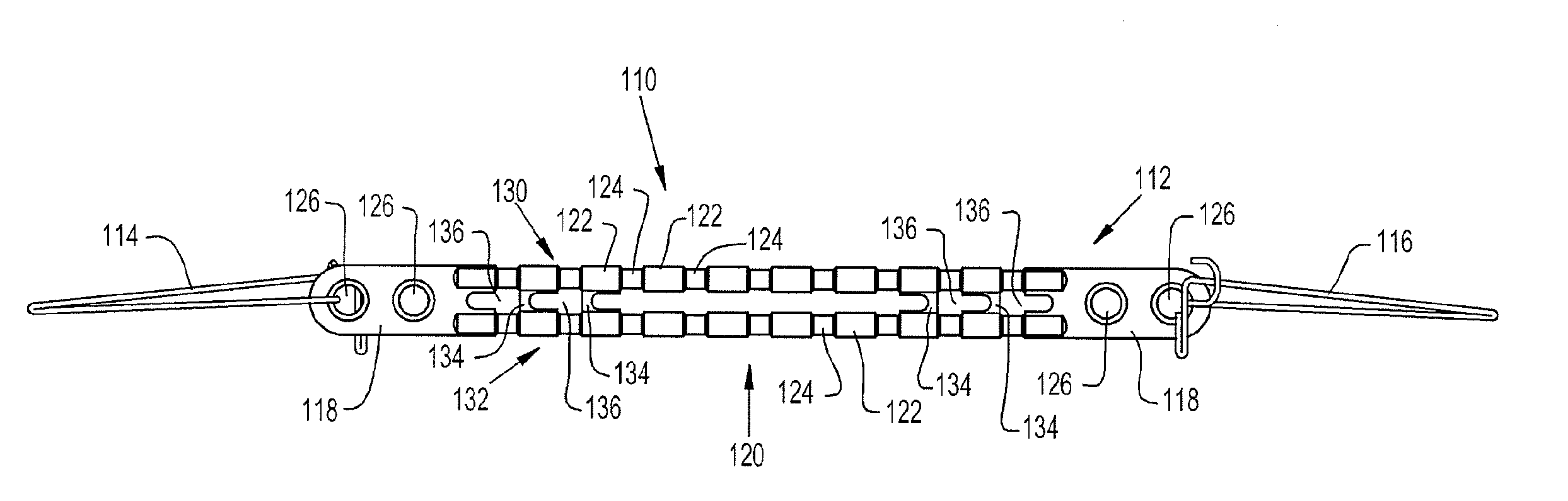
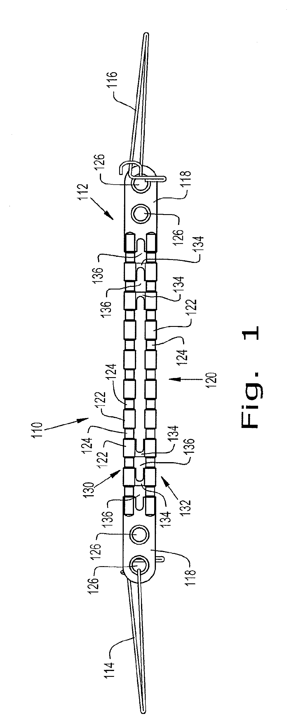
[0039]Referring now more specifically to the drawings and particularly to FIG. 1, an air hose support strap 110 is shown. Support strap 110 generally includes a molded thermoplastic spring 112 and a pair of clips 114, 116 mounted to the thermoplastic spring 112 at opposite ends. The size, shape and configuration of thermoplastic spring 112 may vary from application to application depending, in large part, on the desired characteristics of the finished support strap 110. It should be understood that air hose support strap 110 is merely one exemplary embodiment of a structure that can employ a pre-deformed thermoplastic spring advantageously. Many other applications for pre-deformed thermoplastic springs are contemplated, such as, but not limited to supporting hoses on tractor-trailers, cargo containment straps, office chair tilt and tension members, machine counter balances such on dishwasher doors, etc.

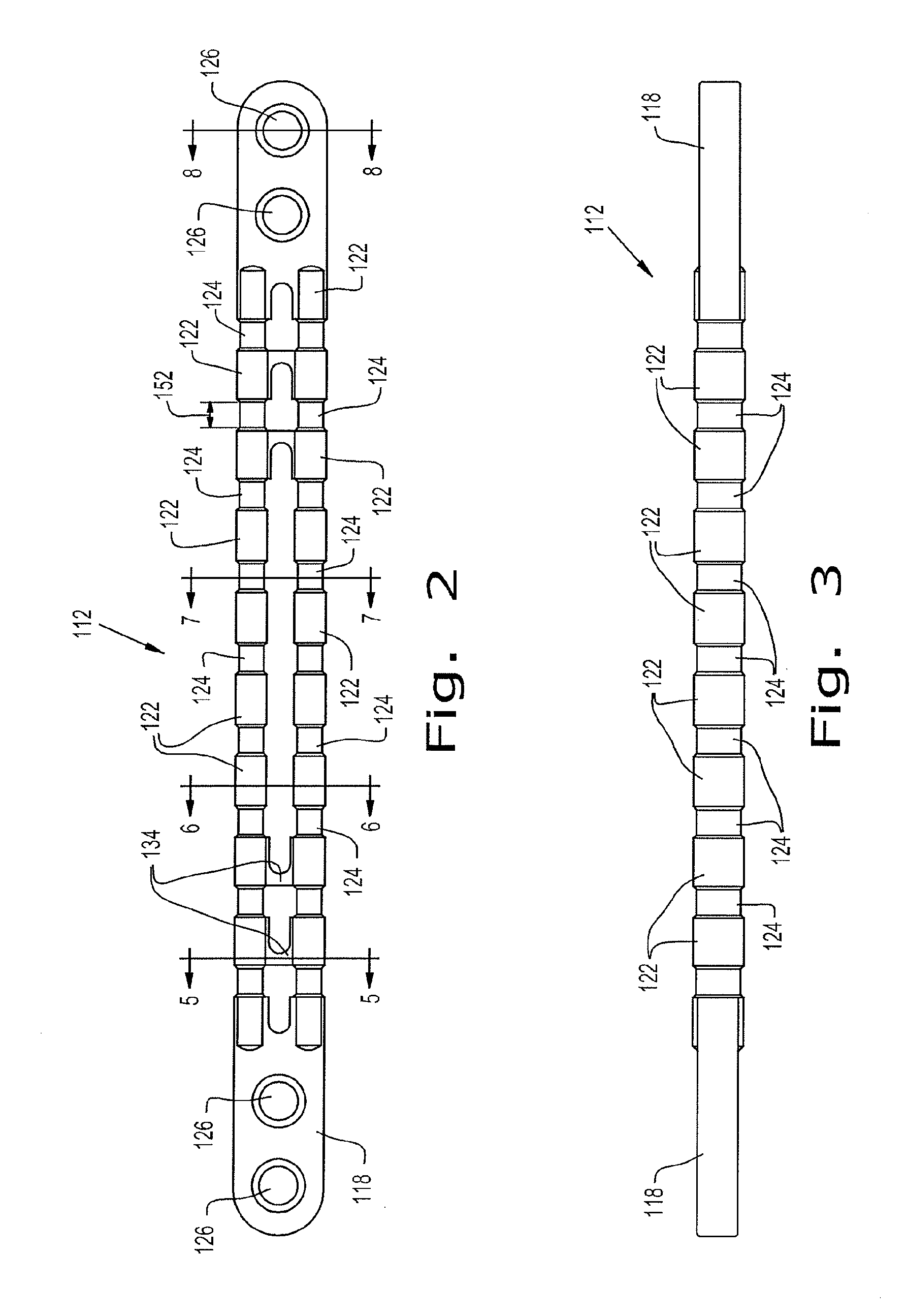
[0040]In the illustrated exemplary embodiment, thermoplastic spring 112 generally...


PUM

PropertyMeasurementUnit
Timeaaaaaaaaaa
Accelerationaaaaaaaaaa
Dimensionaaaaaaaaaa

Abstract

A thermoplastic spring and a method for manufacturing the thermoplastic spring are provided to reduce the effect of creep during use of the spring. The spring is molded and deformed to final dimensions by pre-inducing creep in the molded body.

Description

CROSS-REFERENCE TO RELATED APPLICATIONS[0001]The present application claims the benefits of U.S. Provisional Application Ser. No. 61 / 242,908 filed Sep. 16, 2009; and is a continuation-in-part of U.S. patent application Ser. No. 11 / 423,540 filed Jun. 12, 2006; which is a continuation-in-part of U.S. patent application Ser. No. 11 / 423,220 filed Jun. 9, 2006, (now abandoned); which is a continuation-in-part of U.S. patent application Ser. No. 11 / 112,345 filed Apr. 22, 2005, now U.S. Pat. No. 7,441,758; which claims the benefits of U.S. Provisional Application Ser. No. 60 / 580,648 filed Jun. 17, 2004.FIELD OF THE INVENTION[0002]The present invention relates to thermoplastic springs, and more particularly to molded elastomeric springs, such as railroad air hose support straps, and a method for manufacturing the same,BACKGROUND OF THE INVENTION[0003]It is known to provide spring-loaded mechanical assemblies with a metal coil spring having fabricated end details attached to the spring fro s...

Claims


Application Information

Patent Timeline
IPC IPC(8): F16F1/36F16M13/02B29C55/00
CPCF16F1/46F16F1/376
Inventor COFFIELD, TIMOTHY P.STRATING, ROBERT K.ZIMMERMAN, DEAN A.HARTMANN, ANDREW B.
Owner ILLINOIS TOOL WORKS INC
Why Eureka
Eureka Blog
Learn More