Object image capture apparatus and method

Active Publication Date: 2012-06-21
ELECTRONICS & TELECOMM RES INST
View PDF10 Cites 25 Cited by
  • Summary
  • Abstract
  • Description
  • Claims
  • Application Information

AI Technical Summary

Benefits of technology

[0007]Accordingly, the present invention has been made keeping in mind the above problems occurring in the prior art, and an object of the present invention is to detect a moving object using a method of dividing a wide-area view image into block unit

Problems solved by technology

However, a method of tracking a moving object using a manual operation from among existing methods reaches the limit because the number of cameras increases in geometric progression.
Further, conventional moving object tracking methods are lacking in flexibility in terms of the mutual cooperation between camera apparatuses used to effective

Method used


Image

  • Object image capture apparatus and method
  • Object image capture apparatus and method
  • Object image capture apparatus and method

Examples


Embodiment Construction

[0040]The present invention will be described in detail with reference to the accompanying drawings below. Here, when the description is repetitive and detailed descriptions of well-known functions or configurations would unnecessarily obscure the gist of the present invention, the detailed descriptions will be omitted. The embodiments of the present invention are provided to complete the explanation for those skilled in the art the present invention. Therefore, the shapes and sizes of components in the drawings may be exaggerated to provide a more exact description.

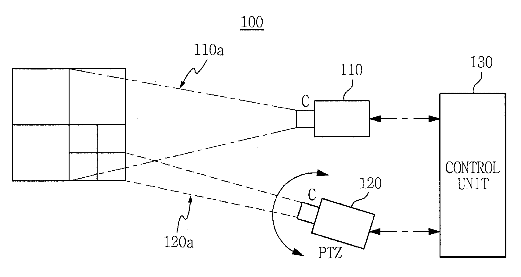
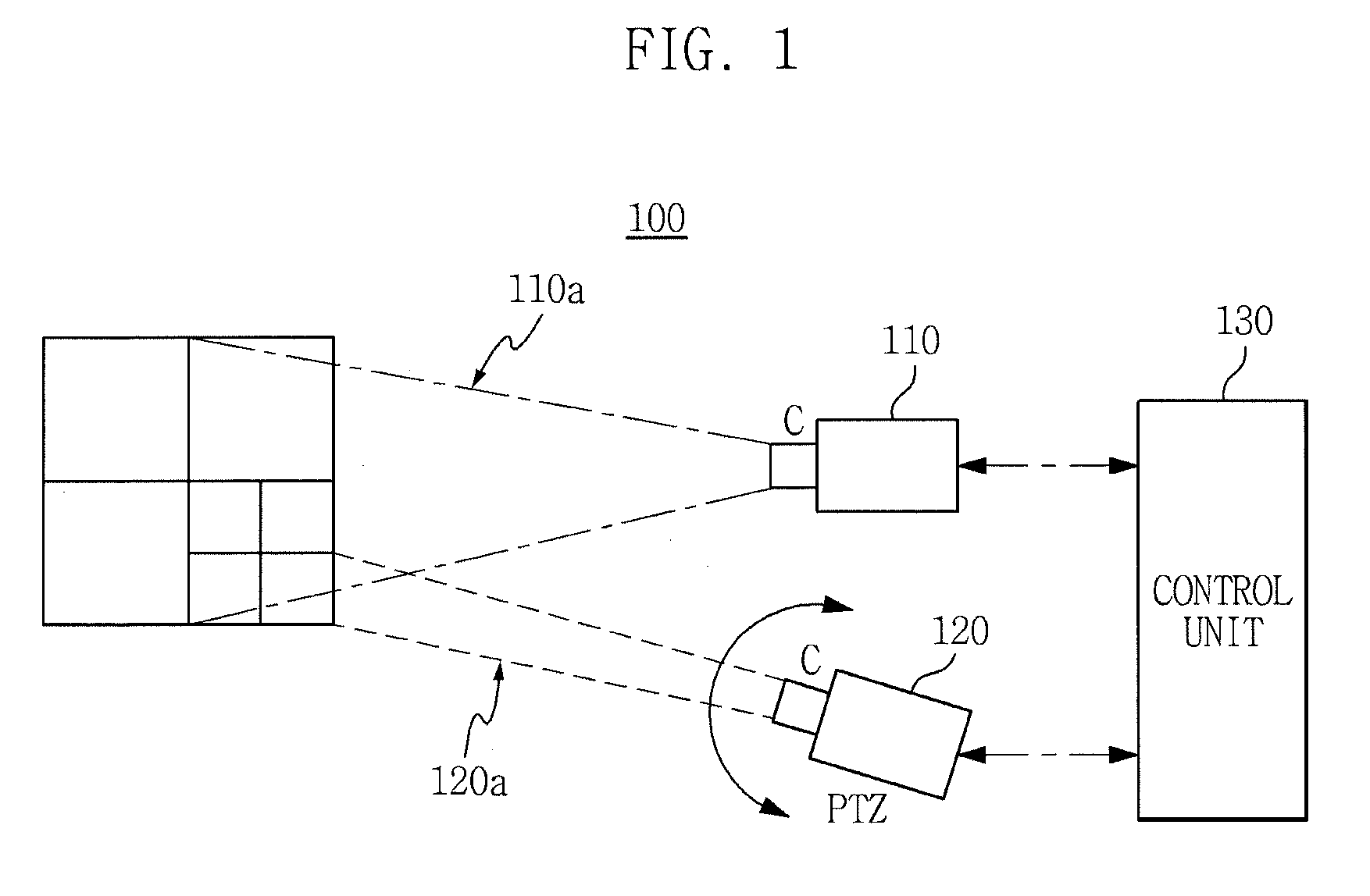
[0041]The configuration and operation of an object image capture apparatus according to the embodiment of the present invention will be described below.

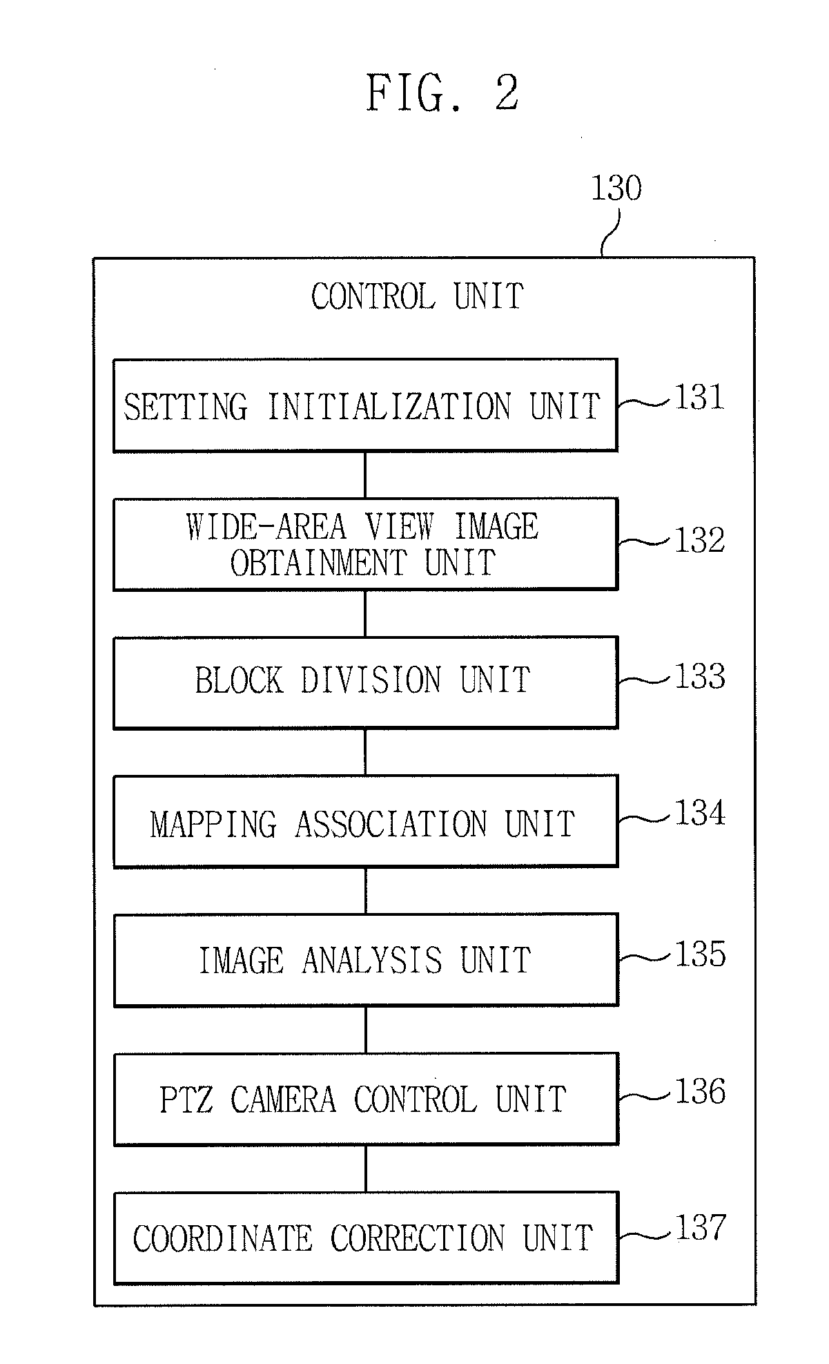
[0042]FIG. 1 is a view illustrating the configuration and operation of an object image capture apparatus according to an embodiment of the present invention in brief FIG. 2 is a block diagram illustrating the configuration of the control unit of the object image capture a...


PUM


Abstract

Disclosed herein is an object image capture apparatus. The object image capture apparatus includes a first camera unit, a second camera unit, and a control unit. The first camera unit obtains a wide-area view image by capturing a wide-area view region. The second camera unit obtains a close-up view image by capturing the close-up view region of the wide-area view region. The control unit controls the second camera unit by dividing the wide-area view image into a plurality of blocks, analyzing the resulting blocks, and defining a target block, in which a moving object is detected, as a close-up view region from among the plurality of blocks.

Description

CROSS REFERENCE TO RELATED APPLICATION[0001]This application claims the benefit of Korean Patent Application No. 10-2010-0131557, filed on Dec. 21, 2010, which is hereby incorporated by reference in its entirety into this application.BACKGROUND OF THE INVENTION[0002]1. Technical Field[0003]The present invention relates generally to an object image capture apparatus and method, and, more particularly, to an object image capture apparatus and method which effectively improves the capture of object information in video surveillance, Human Computer Interaction (HCI), Human Robot Interaction (HRI), and smart appliance fields.[0004]2. Description of the Related Art[0005]Technologies for detecting and tracking an object or an interest region using a video image captured by a camera have been applied to various regions, such as a video surveillance system based on a Closed-Circuit Television (CCTV), a user interface based on a gesture, human identification at a distance, an intelligent vehi...

Claims


Application Information

Patent Timeline
IPC IPC(8): H04N5/247
CPCH04N5/247H04N5/232H04N23/695H04N23/90G06T7/11G06T2207/10028G06T2207/10024H04N7/18
Inventor YOO, JANG-HEEMOON, DAE-SUNGCHUNG, YUN-SU
Owner ELECTRONICS & TELECOMM RES INST
Why Eureka
Try Eureka