
Adjustment device, lens barrel, and optical apparatus

a technology of adjustment device and lens barrel, which is applied in the direction of mountings, instruments, optics, etc., can solve the problems of complicated operation of the axis adjustment device of the conventional lens axis adjustment device, and achieve the effect of simple structure adjustment, easy adjustment work, and high precision

Active Publication Date: 2012-06-21
SAMSUNG ELECTRONICS CO LTD
View PDF1 Cites 11 Cited by
  • Summary
  • Abstract
  • Description
  • Claims
  • Application Information

AI Technical Summary

Benefits of technology

The present invention provides an adjustment device for optical devices that has a simple structure and can easily adjust the position of the device in relation to the optical axis with high precision. The device includes a holding member, a support member, and two rotating members that can be rotated around a fixed point on the support member. The holding member moves within a surface facing the support member, resulting in a relative position adjustment in a direction perpendicular to the optical axis of the device. The invention also provides a lens barrel and an optical apparatus that includes the adjustment device.

Problems solved by technology

However, conventional lens axis adjustment devices have a disadvantage in that when the adjustment device is removed after the adjustment, the lens holding member moves in a direction in which stress applied to the lens holding member is relieved.
Accordingly, an axis adjustment operation of a conventional lens axis adjustment device is complicated.

Method used


Image

  • Adjustment device, lens barrel, and optical apparatus
  • Adjustment device, lens barrel, and optical apparatus
  • Adjustment device, lens barrel, and optical apparatus

Examples


Embodiment Construction

[0021]Reference will now be made in detail to exemplary embodiments of the present general inventive concept, examples of which are illustrated in the accompanying drawings, wherein like reference numerals refer to the like elements throughout. The exemplary embodiments are described below in order to explain the present general inventive concept while referring to the figures.

[0022]Hereinafter, an adjustment device, a lens barrel, and an optical apparatus according to the present general inventive concept will be described in detail with reference to the attached drawings.

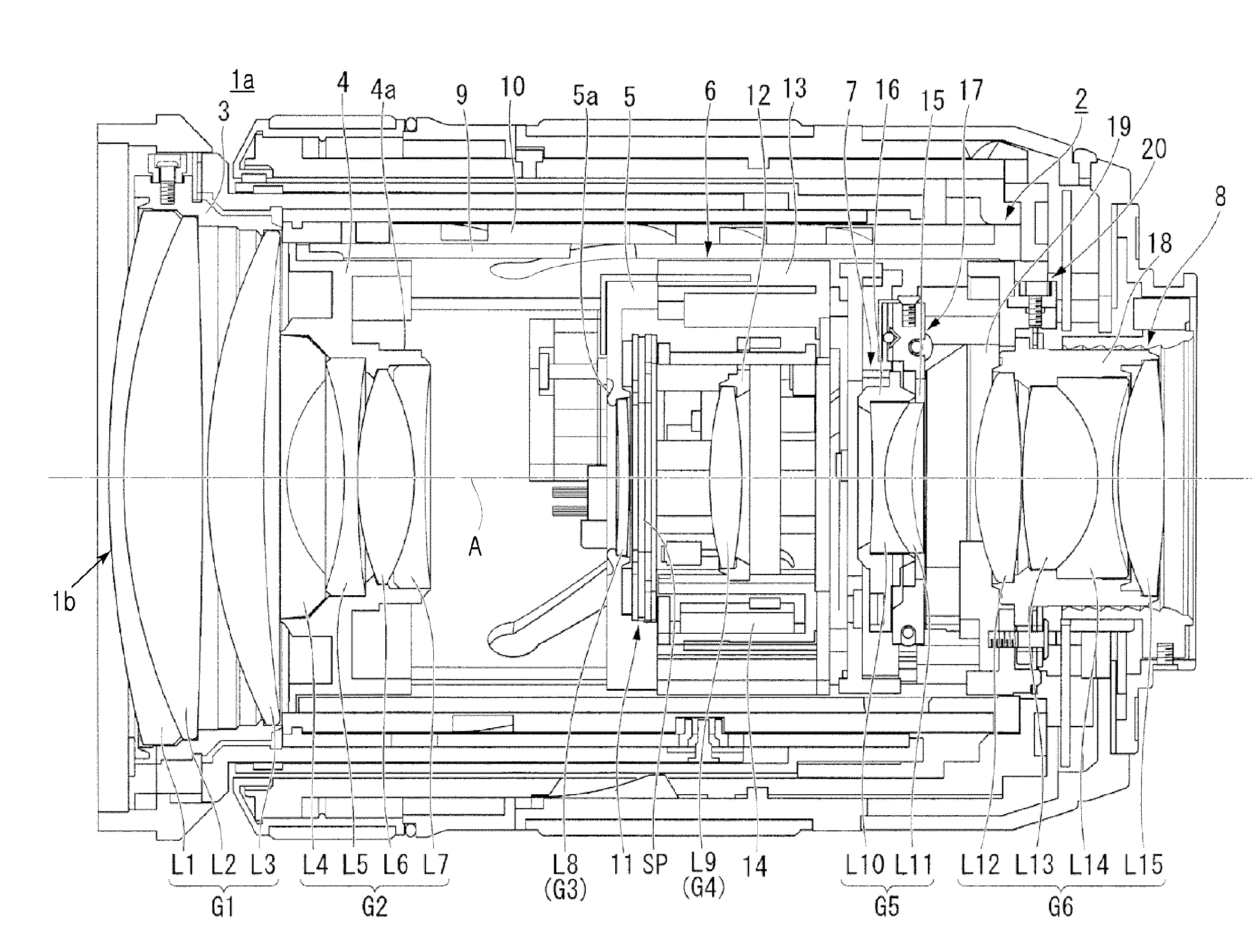
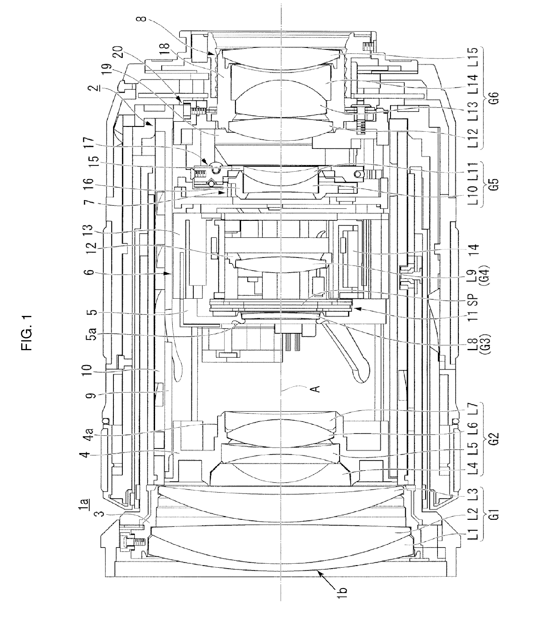
[0023]In at least one exemplary embodiment, an interchangeable lens 1a (i.e., an optical apparatus) is illustrated in FIG. 1. The interchangeable lens 1a may be used, for example, with a single-lens reflex (SLR) camera, as discussed further below. Although a SLR camera is referred to hereinafter, the interchangeable lens 1a may be used with various photographing devices including, but not limited to, a lens shutte...


PUM


Abstract

An axis adjustment device, which may adjust an optical axis mismatch of an optical device at a high precision, and may perform an axis adjustment operation, includes a holding member to hold an optical device, a support member to support the holding member so that the holding member moves within a facing surface, a first rotating member to hold the holding member and rotatably supported around a first point S1 formed at a surface facing the support member, and a second rotating member to hold the holding member and to be rotatably supported around a second point formed at the surface facing the support member. The holding member moves within the surface facing the support member due to a rotation of one of the first and second rotating members and in order to adjust a relative position in a direction orthogonal to an optical axis of the optical device.

Description

CROSS-REFERENCE TO RELATED APPLICATIONS[0001]This application claims priority under 35 U.S.C. §119(a) from Japanese Patent Application No. 2010-283122, filed on Dec. 20, 2010 with the Japanese Intellectual Property Office, and Korean Patent Application No. 2011-0124468, filed on Nov. 25, 2011, with the Korean Intellectual Property Office, the disclosures of each which are incorporated herein by reference.BACKGROUND OF THE INVENTIVE CONCEPT[0002]1. Field of the Inventive Concept[0003]The present general inventive concept relates to an adjustment device to adjust a relative position in a direction orthogonal to an optical axis of an optical device such as a lens or the like, a lens barrel including the adjustment device, and an optical apparatus including the lens barrel.[0004]2. Description of the Related Art[0005]Among a plurality of lenses arranged in a lens barrel, an inner focus type zoom lens is to move a zoom lens (a variator) and a focus lens in an optical axis in order to per...

Claims


Application Information

Patent Timeline
Patent Type & Authority Applications(United States)
IPC IPC(8): G02B15/02G02B7/16
CPCG02B7/003G02B15/06G02B15/10
Inventor SHINOHARA, MITSURU
Owner SAMSUNG ELECTRONICS CO LTD
Learn More