
Overcurrent detection circuit of light emitting module

a detection circuit and light-emitting module technology, applied in the direction of measuring devices, instruments, electrical equipment, etc., can solve the problems of led breakage, thinned, and open or short electrical signals,

Inactive Publication Date: 2012-06-21
SAMSUNG ELECTRO MECHANICS CO LTD
View PDF0 Cites 5 Cited by
  • Summary
  • Abstract
  • Description
  • Claims
  • Application Information

AI Technical Summary

Problems solved by technology

Generally, an LED has more advantages as compared to an existing cold cathode fluorescent, lamp (CCFL) or the like but also has disadvantages in that an electrical open or short may occur as a thickness of a device to which the LED is applied, such as a TV or the like, is thinned.
Meanwhile, a problem may arise in which any one portion of the plurality of LEDs connected in series shorts with the chassis of a TV set or a metal, forming a printed circuit board (PCB) of the LED, due to defects in the LED module or problems in a manufacturing process thereof, in particularly, as a thickness of the TV set using the LEDs is gradually thinly manufactured.
Therefore, the cathode terminal may electrically short with the chassis corresponding to a ground potential to allow overcurrent to flow in the LED module, thereby causing serious problems such as breakage of the LED and breakage of a panel due to overheating of the LED, or the like.

Method used


Image

  • Overcurrent detection circuit of light emitting module
  • Overcurrent detection circuit of light emitting module
  • Overcurrent detection circuit of light emitting module

Examples


Embodiment Construction

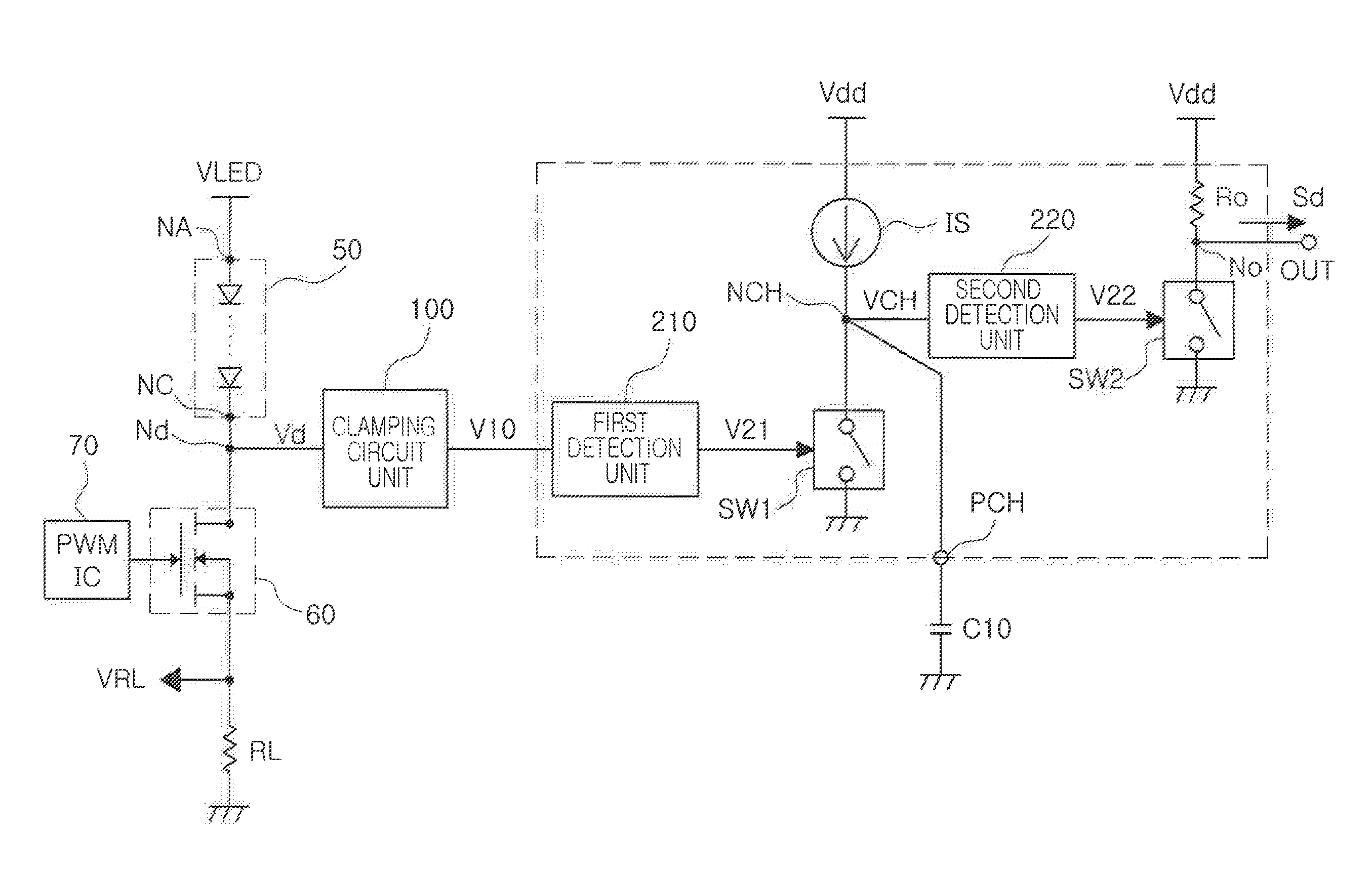
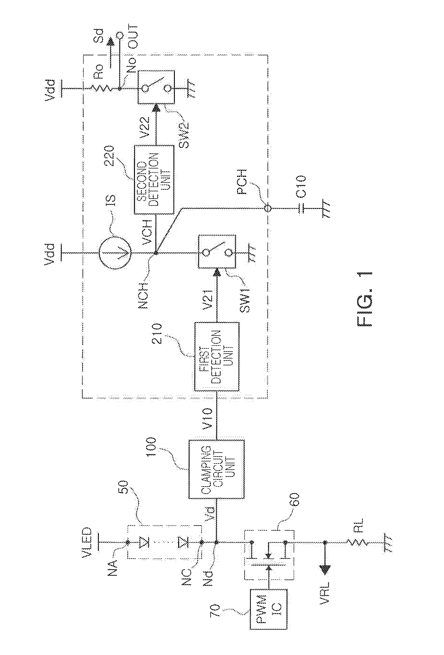
[0028]Exemplary embodiments of the present invention will now be described in detail with reference to the accompanying drawings.

[0029]The present invention should not be limited to the embodiments set forth herein and the embodiments may be used to assist in understanding the technical idea of the present invention. Like reference numerals designate like components having substantially the same constitution and function in the drawings of the present invention.

[0030]FIG. 1 is a configuration diagram of an overcurrent detention circuit of a light emitting module according to an exemplary embodiment of the present invention.

[0031]Referring to FIG. 1, an overcurrent detection circuit of a light emitting module according to an exemplary embodiment of the present invention may include a damning circuit unit 100 detecting a detection voltage Vd from a detection connection node Nd connected to a cathode terminal NC of a light emitting module 50 including at least one light emitting elemen...


PUM


Abstract

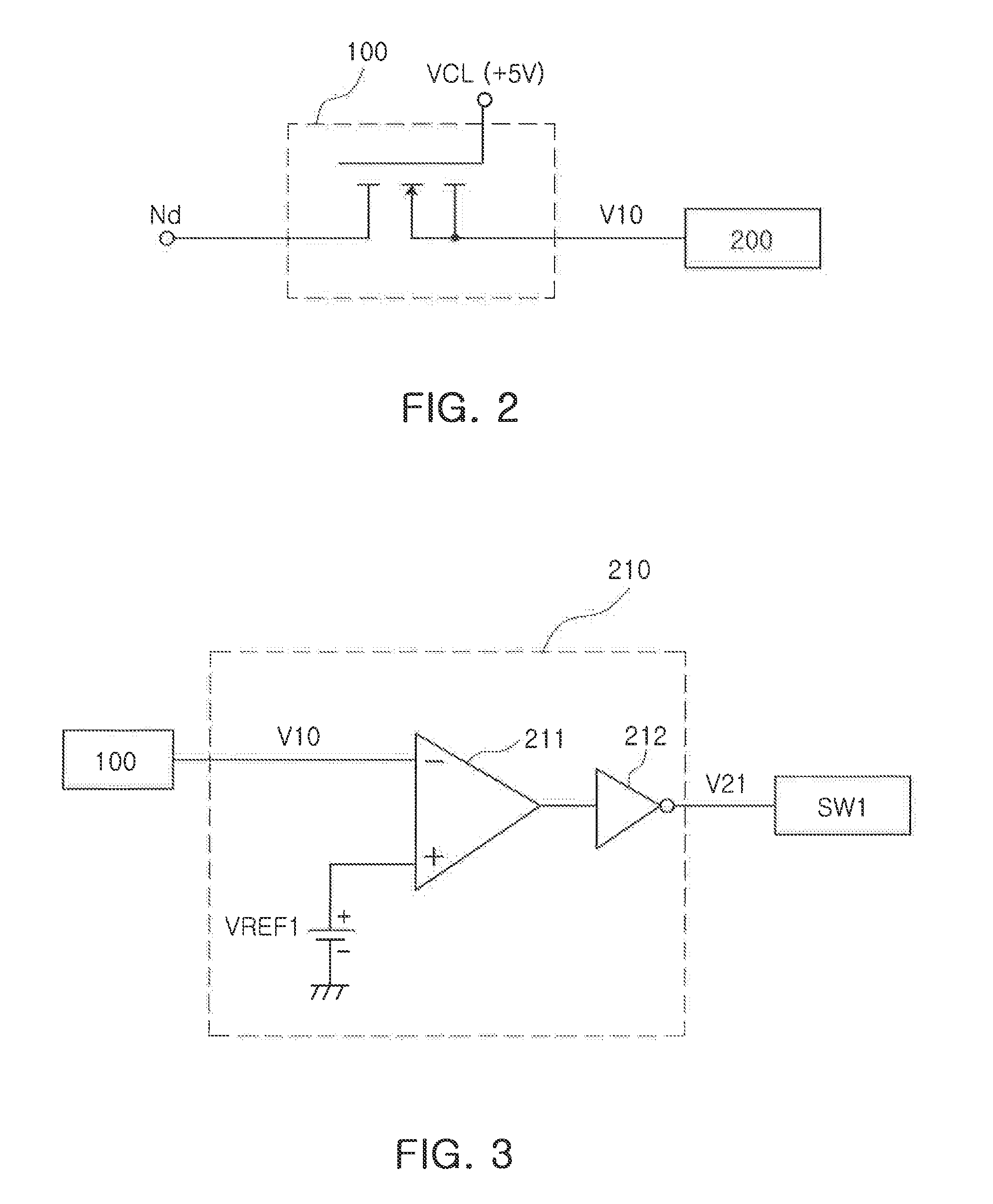
There is provided an overcurrent detection circuit of a light emitting module, including: a clamping circuit unit 100 detecting a detection voltage Vd from a detection connection node Nd connected to a cathode terminal NC of a light emitting module 50 including at least one light emitting element and clamping the detection voltage Vd to a preset clamping voltage VCL; and an abnormality detection unit 200 determining a voltage V10 clamped by the clamping circuit unit 100 to be overcurrent and generating an overcurrent detection signal, when the voltage clamped by the clamping circuit unit is lower than a preset first reference voltage VREF1.

Description

CROSS-REFERENCE TO RELATED APPLICATIONS[0001]This application claims the priority of Korean Patent Application No. 10-2010-0131866 filed on Dec. 21, 2010, in the Korean Intellectual Property Office, the disclosure of which is incorporated herein by reference.BACKGROUND OF THE INVENTION[0002]1. Field of the Invention[0003]The present invention relates to an overcurrent detection circuit of a light emitting device capable of detecting overcurrent due to abnormal operating conditions in a light emitting module that may be applied to a TV or a display.[0004]2. Description of the Related Art[0005]Generally, with the increase in interest in an LED-TV using a light emitting diode (LED) as a light source, research into a LED module used as a backlight light source has been also variously conducted. Accordingly, a driver circuit driving the LED module has been also variously researched and developed.[0006]Generally, an LED has more advantages as compared to an existing cold cathode fluoresce...

Claims


Application Information

Patent Timeline
Patent Type & Authority Applications(United States)
IPC IPC(8): H02H9/02
CPCG01R19/16571
Inventor KIM, JIN HWANJANG, YOUNG SUCHOI, HEUNG GYOONKIM, SUNG HO
Owner SAMSUNG ELECTRO MECHANICS CO LTD
Learn More