
Imaging apparatus and lens unit

a technology of imaging apparatus and lens unit, which is applied in the field of imaging apparatus, can solve the problems of insufficient improvement of communication performance of lens microcomputer, frequent communication interrupt of lens microcomputer, and inability to improve communication performance of camera microcomputer. to achieve the effect of improving the operation performance of the camera

Inactive Publication Date: 2012-06-21
CANON KK
View PDF3 Cites 38 Cited by
  • Summary
  • Abstract
  • Description
  • Claims
  • Application Information

AI Technical Summary

Benefits of technology

[0009]Exemplary embodiments of the present invention are directed to a camera system that can improve operation performances of a camera and an interchangeable lens, even when the interchangeable lens is an old type lens operable according to a conventional communication method only.

Problems solved by technology

During the waiting time (Busy), the lens microcomputer does not accept any communication data transmitted from the camera.
Therefore, communication performances of the camera microcomputer cannot be improved sufficiently.
On the other hand, the lens microcomputer frequently receives a communication interrupt from the camera.
When an interrupt signal is received from the camera, the lens microcomputer prioritizes communication interrupt processing over other processing to output a “Busy signal” and subsequently cancel the “Busy signal.” Therefore, communication performances of the lens microcomputer cannot be improved sufficiently.

Method used


Image

  • Imaging apparatus and lens unit
  • Imaging apparatus and lens unit
  • Imaging apparatus and lens unit

Examples


Embodiment Construction

[0030]Various exemplary embodiments, features, and aspects of the invention will be described in detail below with reference to the drawings.

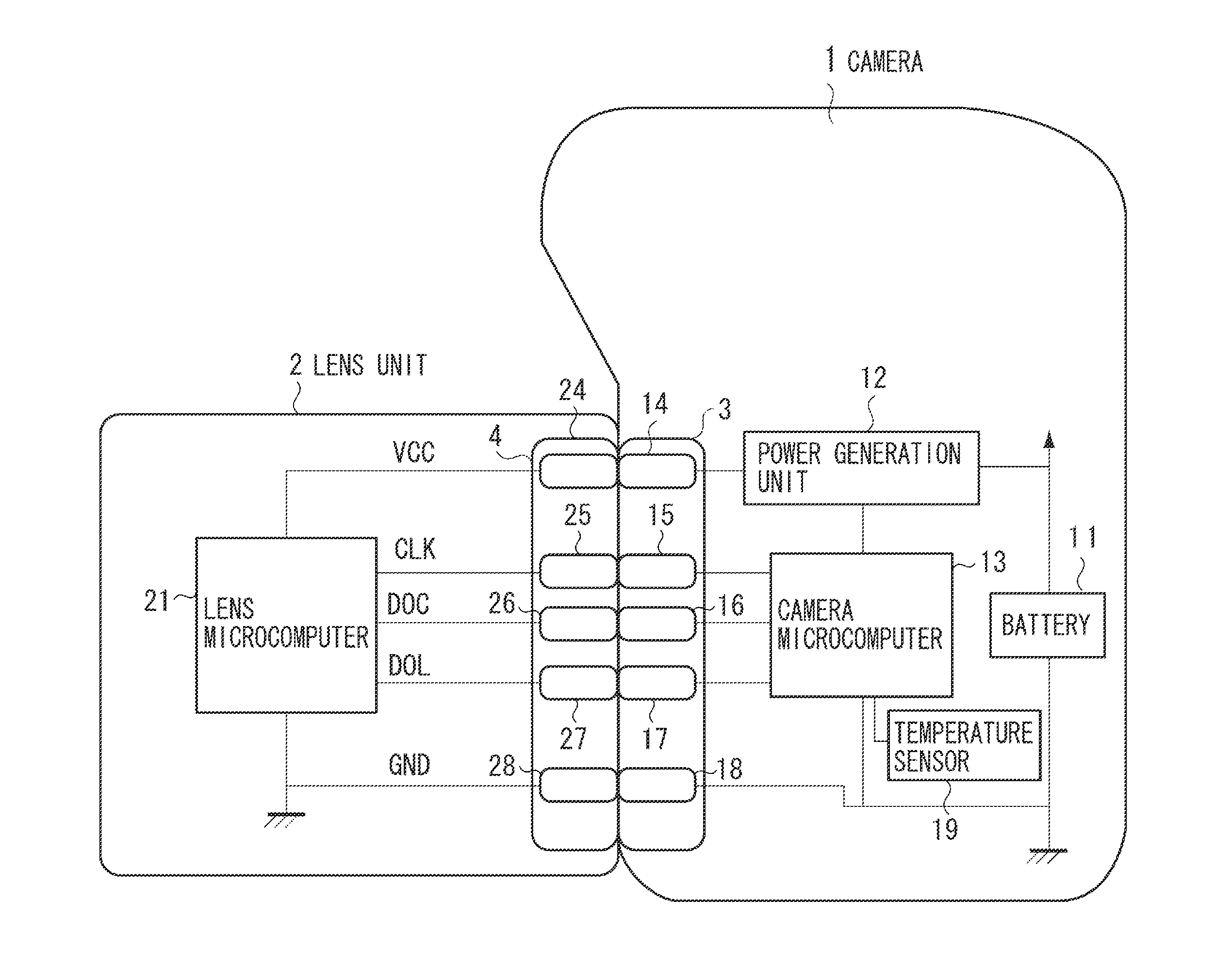
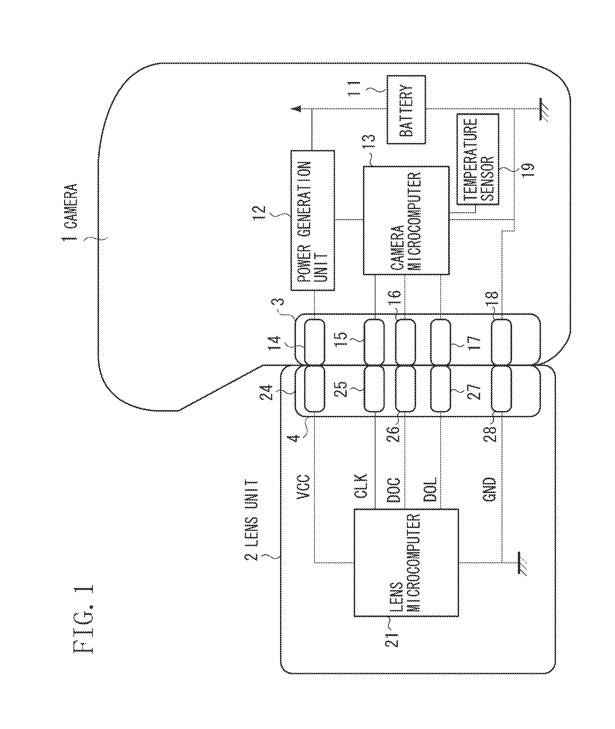
[0031]A first exemplary embodiment of the present invention is described below. FIG. 1 illustrates a circuit configuration including a camera 1 and an interchangeable lens unit 2 according to an exemplary embodiment of the present invention. In FIG. 1, the interchangeable lens unit 2 is detachably mounted on the camera 1 that serves as an imaging apparatus . The camera 1 has a mounting portion 3 serving as a connection portion. The lens unit 2 has a lens mount portion 4 serving as an accessory connection portion. The camera 1 includes a battery 11, a power generation unit 12, and a camera microcomputer 13 provided in the body thereof.

[0032]The battery 11 can generate a predetermined voltage, which can be supplied to the power generation unit 12. The power generation unit 12 can generate and supply an optimum power voltage to enable each electri...


PUM


Abstract

An imaging apparatus includes a first terminal and a second terminal and a control unit configured to perform switching between a first communication mode for outputting a clock signal via the first terminal and communicating with a mounted lens unit via the second terminal based on the clock signal and a second communication mode for communicating with the mounted lens unit via the first terminal or the second terminal without using the clock signal. The control unit continuously sets the first communication mode if the second communication mode is not usable for the mounted lens unit. On the other hand, the control unit sets the second communication mode if the second communication mode is available for the mounted lens unit and sets a baud rate to communicate with the lens unit in the second communication mode to be a baud rate value received from the lens unit.

Description

BACKGROUND OF THE INVENTION[0001]1. Field of the Invention[0002]The present invention relates to an imaging apparatus that can communicate with a lens unit to transmit and receive information and a lens unit that can be detachably mounted on the imaging apparatus.[0003]2. Description of the Related Art[0004]A clock synchronous type serial communication method (i.e., a synchronous serial communication method) has been conventionally employed for communications to be performed between a camera and a lens unit in an interchangeable lens system. A conventional technique discussed in Japanese Patent Application Laid-Open No. 9-304804 includes performing synchronous serial communications at a first baud rate so that a camera can communicate with a mounted lens unit even when the lens unit is an old type. If communication contents reveal that a mounted lens unit is a new type, then the method includes starting synchronous serial communications at a second baud rate that is higher than the ...

Claims


Application Information

Patent Timeline
IPC IPC(8): G03B17/00
CPCG03B17/14
Inventor OSAWA, TOSHIFUMI
Owner CANON KK
Learn More