Continuous flow thermodynamic pump

a thermodynamic pump and continuous flow technology, applied in the direction of positive displacement liquid engines, machine/engines, containers, etc., can solve the problems of complex prior mechanical lh2 pumping systems supplying liquid to conventional heat exchangers for conversion to gas, and insufficient reliability for extended us

Active Publication Date: 2012-06-21
THE BOEING CO
View PDF5 Cites 12 Cited by
  • Summary
  • Abstract
  • Description
  • Claims
  • Application Information

AI Technical Summary

Problems solved by technology

However, reasonable storage densities for hydrogen can only be achieved with cryogenic storage as a liquid.
Without a suitable pump, the vehicle will not be able to meet the long endurance requirements of HALE vehicles.
Pr

Method used


Image

  • Continuous flow thermodynamic pump
  • Continuous flow thermodynamic pump
  • Continuous flow thermodynamic pump

Examples


Embodiment Construction

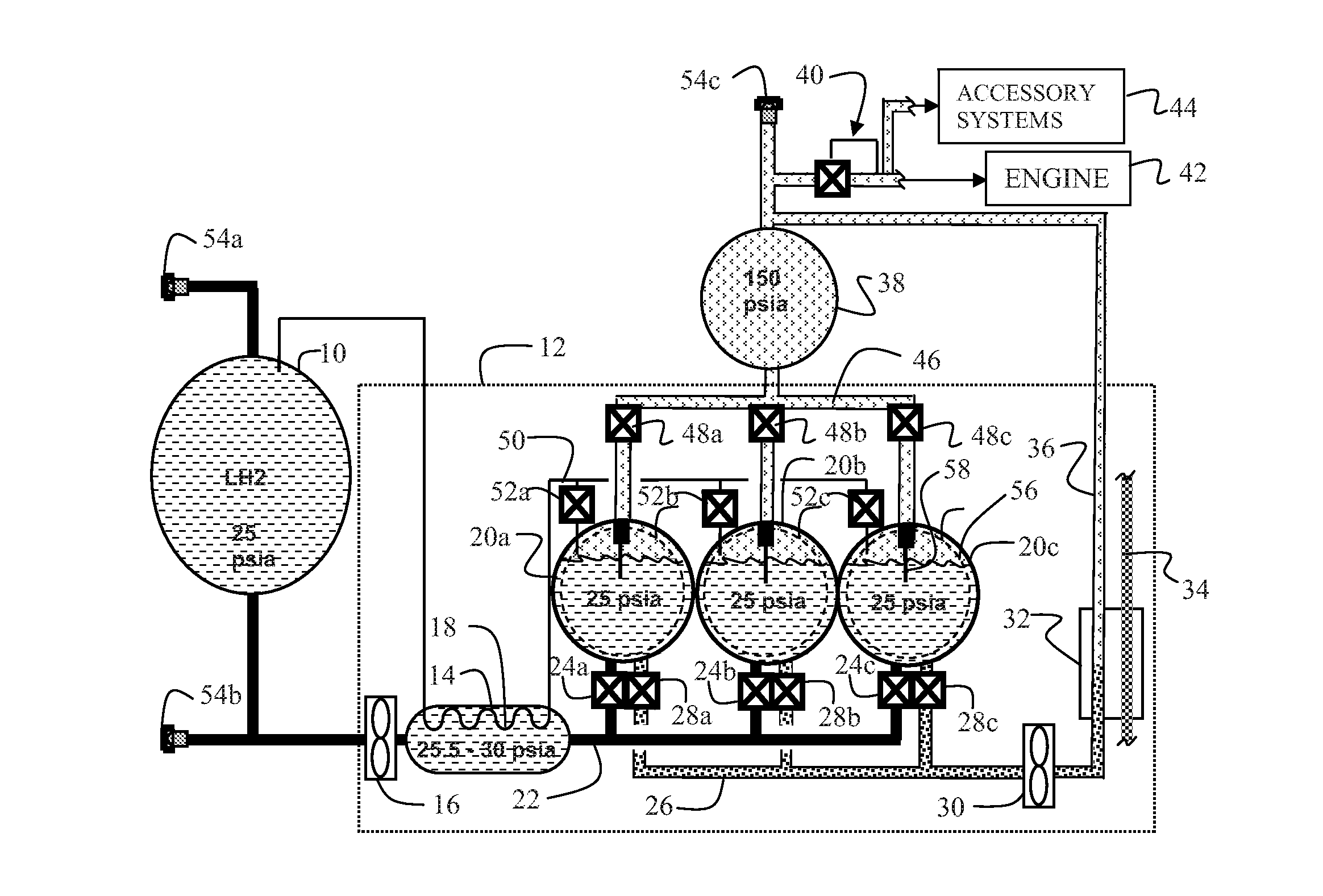
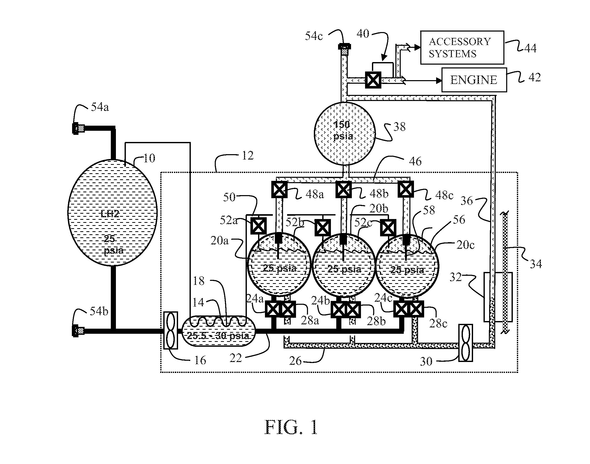
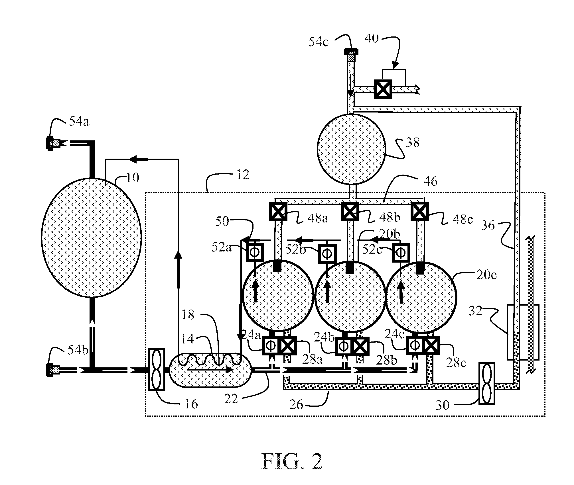
[0012]Referring to FIG. 1, the embodiments described herein demonstrate a system for storage of LH2 and supply of GH2 by a thermodynamic pump to an engine and / or other accessory systems through a proportional flow control device. For an exemplary embodiment, a LH2 storage dewar 10 stores LH2 for the system. While one dewar is shown, multiple dewars may be employed for alternative embodiments requiring additional LH2 storage capability. A thermodynamic pump (TDP) 12 incorporates a LH2 transfer accumulator and return GH2 condenser 14 receiving LH2 from dewar 10 through a first boost pump 16 and returning GH2 to the dewar through a first heat exchanger 18 in the accumulator condenser. Multiple TDP tanks shown for the embodiment described as spheres 20a, 20b and 20c receive LH2 from the LH2 transfer accumulator through a liquid fill manifold 22 having inlet valves 24a, 24b and 24c into the respective spheres. Each sphere provides LH2 to a liquid supply manifold 26 through supply valves ...


PUM


Abstract

A thermodynamic pump for provides gaseous hydrogen employing a plurality of liquid hydrogen (LH2) tanks sequentially pressurized with gaseous hydrogen (GH2) from an accumulator. A heat exchanger receiving LH2 from each of the plurality of tanks as sequentially pressurized returns pressurized GH2 to the accumulator for supply to an engine.

Description

BACKGROUND INFORMATION[0001]1. Field[0002]Embodiments of the disclosure relate generally to cryogenic pumping systems and more particularly to embodiments for a system employing multiple thermodynamic pumping chambers sequentially receiving cryogenic liquid from a tank and interconnected though a heat exchanger to a gas supply tank for continuous gas supply.[0003]2. Background[0004]The use of liquid hydrogen, LH2, for higher density storage and the conversion of LH2 to gaseous hydrogen (GH2) for use in reciprocating and other internal combustion engines is a growing requirement. As an exemplary use, the need for high altitude long endurance (HALE) type Unmanned Aerial Vehicles with large reciprocating engines is growing exponentially and may soon reach 3,000 vehicles per year. Use of hydrogen for fueling these vehicles has been demonstrated as an efficient and environmentally friendly solution. However, reasonable storage densities for hydrogen can only be achieved with cryogenic st...

Claims


Application Information

Patent Timeline
IPC IPC(8): F04B19/24
CPCF17C5/06F17C2250/0636Y02E60/321F17C2201/0128F17C2205/0142F17C2205/0146F17C2205/0323F17C2205/0338F17C2221/012F17C2223/0153F17C2223/033F17C2225/0123F17C2225/035F17C2227/0135F17C2227/0388F17C2227/04F17C2250/01F17C9/02F17C13/00F17C13/04F17C2223/013F17C2227/0107F17C2227/0304F17C2227/0393F17C2227/042F17C2270/0186Y02P90/45F17C2227/0302F17C2265/066Y10T137/0318Y02E60/32B64D37/30B64D37/02F17C7/04
Inventor WATTS, DANIEL A.
Owner THE BOEING CO
Why Eureka
Try Eureka