Tank System For The Cryogenic Storage Of Hydrogen, And Aircraft With A Tank System For The Cryogenic Storage Of Hydrogen

a technology for cryogenic storage and tanks, which is applied in the direction of specific fuel fuel fuel systems, vessel construction details, transportation and packaging, etc., can solve the problems of posing a technical challenge, the inability to carry cryogenic hydrogen along, and so as to counteract the stress on the pressure vessel and high the overall strength of the hollow body

Inactive Publication Date: 2015-11-26
AIRBUS OPERATIONS GMBH
View PDF7 Cites 23 Cited by
  • Summary
  • Abstract
  • Description
  • Claims
  • Application Information

AI Technical Summary

Benefits of technology

[0024]Advantageously, interspaces between adjacent pressure vessels are sealed off in a gas-proof manner and are designed to receive or deliver hydrogen as required. In the dense package of individual pressure vessels, which preferably have a round cross section, interspaces between the individual pressure vessels always remain. Said interspaces may also be used for receiving hydrogen, for example by bonding the adjacent pressure vessels and consequently the gas-proof nature of the interspaces. In addition, the pressure of the hydrogen in the interspaces acts on the exterior surfaces of the individual pressure vessels so that this counteracts the stress on the pressure vessels.
[0025]In a tank system the at least one hollow body may also comprise an exterior wall that extends over a spatial lattice structure. The term “spatial lattice structure” refers to a compound structure comprising regularly arranged struts that for receiving bending loads, compressive lo

Problems solved by technology

If large volume flows or mass flows of hydrogen are required by means of which, for example, turbojet engines or fuel cells of a high nominal output are operated, the carrying along of cryogenic hydrogen is almost unavoidable.
However, the integration of a tank for storing cryogenic hydrogen, for example in an a

Method used


Image

  • Tank System For The Cryogenic Storage Of Hydrogen, And Aircraft With A Tank System For The Cryogenic Storage Of Hydrogen
  • Tank System For The Cryogenic Storage Of Hydrogen, And Aircraft With A Tank System For The Cryogenic Storage Of Hydrogen
  • Tank System For The Cryogenic Storage Of Hydrogen, And Aircraft With A Tank System For The Cryogenic Storage Of Hydrogen

Examples


Embodiment Construction

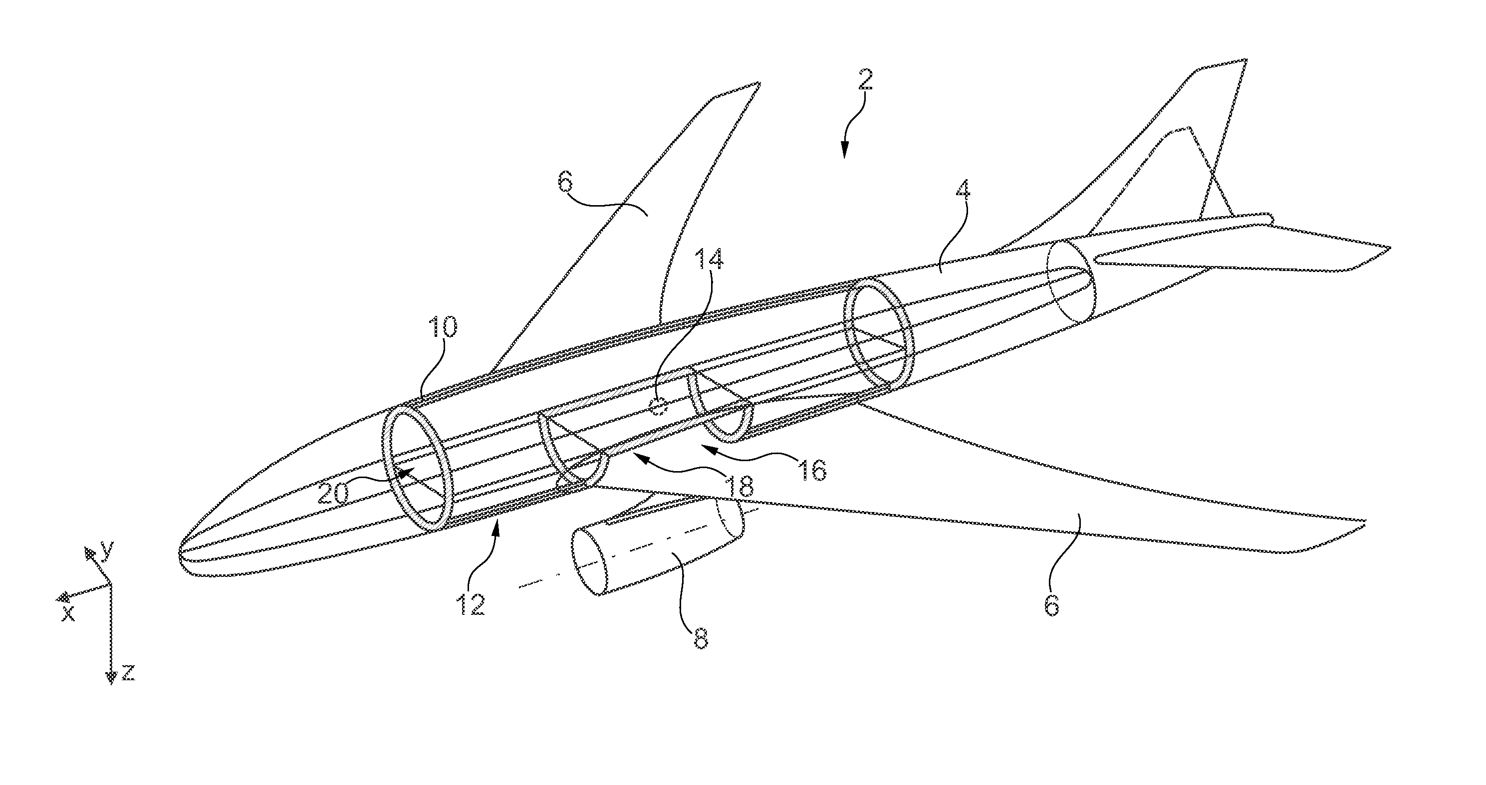
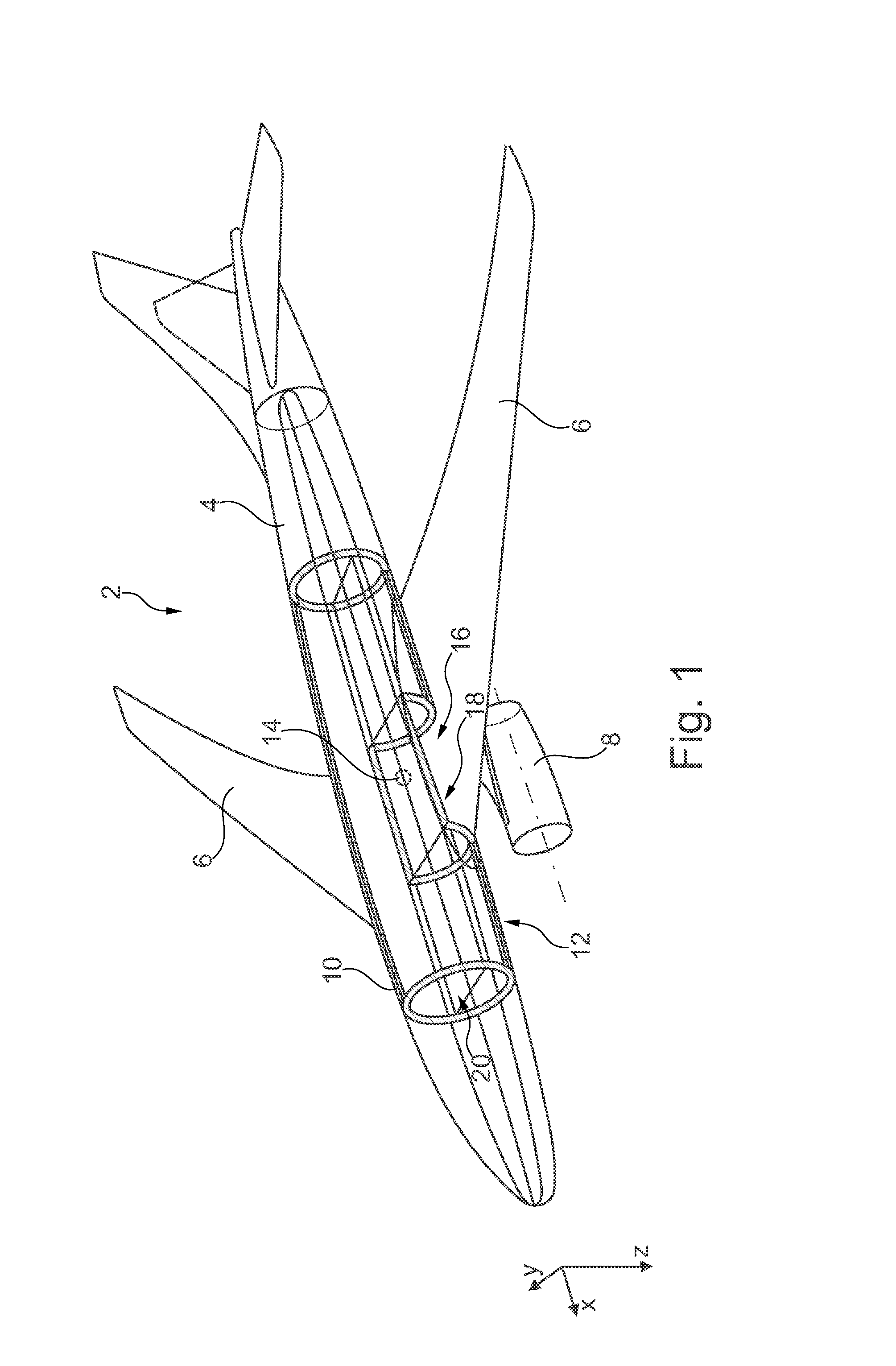
[0054]FIG. 1 shows an aircraft 2 with an elongated, essentially cylindrical, fuselage 4, wings 6 arranged thereon, and engines 8 arranged on the undersides of the wings 6. The aircraft fuselage 4 comprises a primary structure (not explicitly shown in FIG. 1) that extends over the entire fuselage 4. The primary structure is designed to ensure the structural stability of the fuselage 4 during all the operating phases of the aircraft 2.

[0055]Part of the primary structure is supplemented or replaced by a tank structure 10 of a tank system 12, wherein the tank structure 10 uniformly extends from the center of gravity 14 of the aircraft 2 in the longitudinal direction (x) both forwards, i.e. in the direction of the nose, and rearwards, i.e. in the direction of the tail, and is designed so as to be hollow cylindrical. The structural design of the tank structure 10 is to be matched in such a manner that the structural stability of the aircraft 2 is comparable to that of conventional aircraf...


PUM


Abstract

A tank system for the cryogenic storage of hydrogen includes a tank structure with at least one hollow body for accommodating liquid hydrogen and at least one insulating means, which encloses the tank structure, for insulating the at least one hollow body. The tank structure has an exterior shape that is integrateable in a load-bearing primary structure of an aircraft. The tank structure is load bearing and is designed to at least partially absorb a load introduced into the primary structure. This makes it possible to achieve a particularly efficient design of an aircraft in which the fuselage of the aircraft is not divided into two parts by the hydrogen tank integrated therein, can be arranged near the center of gravity, and essentially does not increase the additional weight of the aircraft.

Description

TECHNICAL FIELD[0001]The invention relates to a tank system for the cryogenic storage of hydrogen and to an aircraft with a tank system, installed therein, for the cryogenic storage of hydrogen.BACKGROUND OF THE INVENTION[0002]The operation of hydrogen-consuming devices in vehicles makes it necessary to carry hydrogen along or to continuously produce it. If large volume flows or mass flows of hydrogen are required by means of which, for example, turbojet engines or fuel cells of a high nominal output are operated, the carrying along of cryogenic hydrogen is almost unavoidable. A vessel for storing cryogenic hydrogen over a particular period of time not only requires adequate insulation, because liquid hydrogen has a temperature of −253° C. or less, but also adequate pressure resistance of the tank concerned. Vacuum insulation can provide adequate insulation for such a tank, wherein its efficiency is, in particular, increase by the provision of a particularly small surface relative t...

Claims


Application Information

Patent Timeline
IPC IPC(8): B64D37/06B64D37/32
CPCB64D37/32B64D37/06B64D37/04B64D37/30F17C3/00F17C2201/0104F17C2201/0128F17C2201/0147F17C2201/0152F17C2201/0157F17C2201/0166F17C2201/0171F17C2201/054F17C2203/013F17C2203/0304F17C2203/0391F17C2221/012F17C2223/0161F17C2223/033F17C2260/018F17C2270/0189Y02E60/32Y02T50/40Y02T90/40
Inventor SCHUMACHER, MARKUSHOFFJANN, CLAUSLEHMBERG, FRANK
Owner AIRBUS OPERATIONS GMBH
Why Eureka
Try Eureka