Screw compressor

a compressor and screw technology, applied in the direction of machines/engines, mechanical equipment, liquid fuel engines, etc., can solve the problems of compressor main body damage, compressor failure to completely close the suction channel with the suction adjustment valve, and the compressor cannot complete the operation, so as to prevent excessive wear, avoid frequent connection and disconnection of the clutch mechanism, and reduce electric power consumption and power loss

Active Publication Date: 2012-06-21
KOBELCO COMPRESSORS CORP
View PDF8 Cites 16 Cited by
  • Summary
  • Abstract
  • Description
  • Claims
  • Application Information

AI Technical Summary

Benefits of technology

[0010]It is an object of the present invention to provide a screw compressor that reduces power losses under a state in which the supply of compressed gas is hardly required.
[0012]According to this configuration, when a discharge pressure value detected by the pressure sensor becomes higher than a unload set value that is predetermined, the controller controls the clutch mechanism to be switched to the off-state. When the clutch mechanism is switched to the off-state, the connection between the output shaft of the driving machine and the input shaft of the compressor main body is disconnected. Consequently, when the supply of compressed gas is hardly required, the driving machine and the screw rotor which is the target to be driven by the driving machine are completely disconnected. That is, even if the driving machine continues to be operated, it can be operated under almost no load. Thus, the electric power consumption and power losses are reduced.
[0013]It is preferable that when the discharge pressure value becomes equal to or less than a value slightly lower than the unload set value, the controller switches the clutch mechanism from the off-state to the on-state. Alternatively, it is preferable that when the clutch mechanism is switched to the on-state or the off-state, the controller maintains the switched state of the clutch mechanism until a predetermined time period passes from the time of the switching. According to these configurations, when the discharge pressure value becomes equal to or less than a value slightly lower than the unload set value, the controller switches the clutch mechanism from the off-state to the on-state, or when the clutch mechanism is switched to the on-state or the off-state, the controller maintains the switched state until a predetermined time period passes from the time of the switching. Thus, frequent occurrences of connection and disconnection of the clutch mechanism can be avoided.
[0014]It is preferable that the screw compressor further includes a means that counts the number of times that the clutch mechanism is switched to the on-state except for the switching to the on-state at start-up, and gives an alarm when the number of counted times exceeds a predetermined threshold. According to this configuration, since an alarm is generated when the number of counted times of the connections of the clutch mechanism exceeds the predetermined threshold, the clutch mechanism is prevented from experiencing excessive wear.

Problems solved by technology

However, the above compressor cannot completely close a suction channel with the suction adjustment valve, even in case of unload operation in which compressed gas is not required on the consuming side.
As a result, the operation cannot be continued, and, in the worst case, the compressor main body is damaged.
Thus, even in the unload operation, the suction adjustment valve cannot be completely closed, and 20 to 30% of the power that is consumed in load operation is unfortunately wasted.

Method used


Image

  • Screw compressor
  • Screw compressor

Examples


Embodiment Construction

[0016]An embodiment of the present invention is now described with reference to the accompanying drawing.

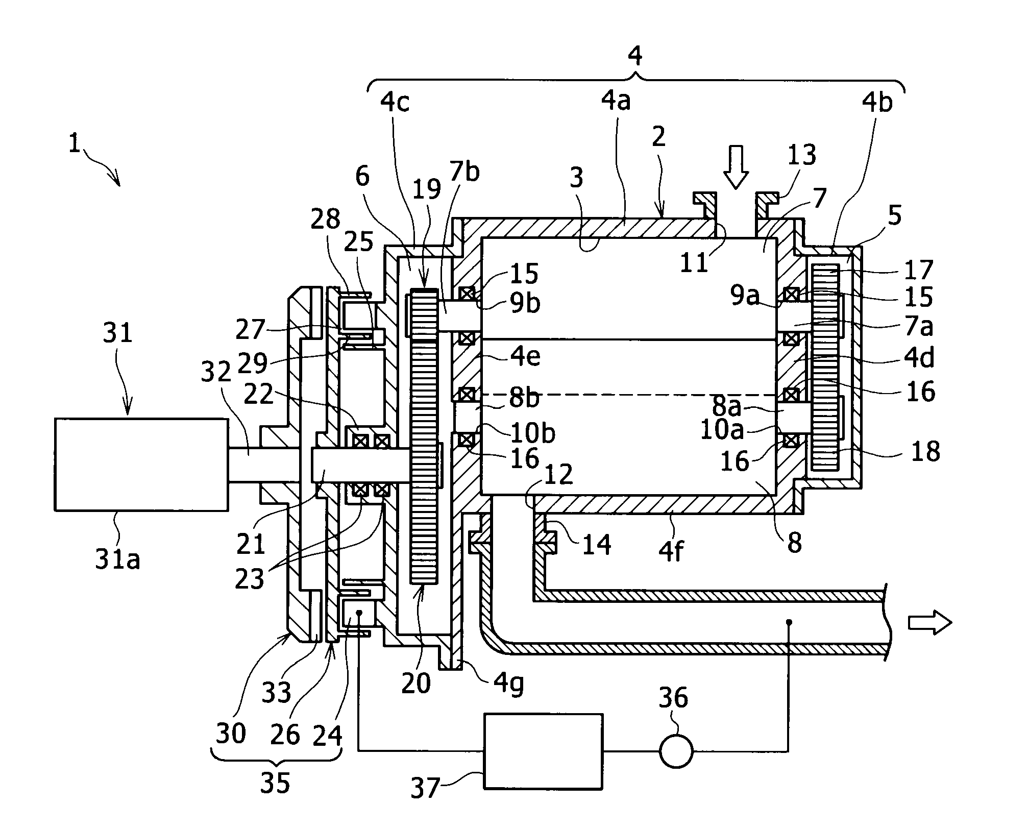
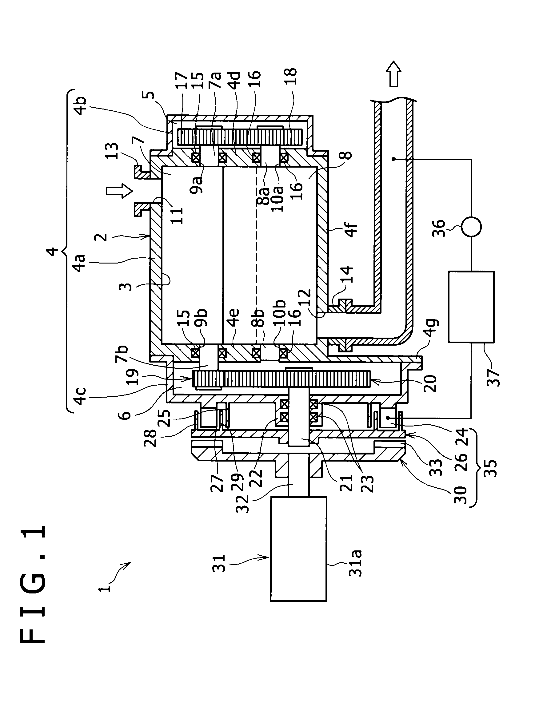
[0017]FIG. 1 shows a screw compressor 1 according to the present invention. The screw compressor 1 includes a compressor main body 2, a clutch mechanism 35, a motor (driving machine) 31 and a controller 37.

[0018]The compressor main body 2 includes a casing 4. The casing 4 includes: a main casing 4a, in which a compression chamber 3 is formed; an end cover 4b for synchronizing gears, which is mounted to one side of the main casing 4a to form a gear compartment 5 between the end cover 4b and the main casing 4a; and an end cover 4c for transmission, which is mounted to the other side of the main casing 4a to form a gear compartment 6 between the end cover 4c and the main casing 4a.

[0019]In the compression chamber 3 of the main casing 4a, a male screw rotor 7 and a female screw rotor 8 that are engaged with each other are rotatably accommodated.

[0020]A rotor shaft 7a extends from th...


PUM


Abstract

A screw compressor including a driving machine having an output shaft coupled to an input shaft of a compressor main body; a clutch mechanism between the output shaft of the driving machine and the input shaft of the compressor main body; a pressure sensor installed in a discharge channel; and a controller that controls the switching of the clutch mechanism between an engaged state and a disengaged state based on a discharge pressure value detected by the pressure sensor is disclosed. When the discharge pressure value becomes higher than an unload set value that is predetermined, the controller controls the clutch mechanism to be switched to the disengaged state. According to the above screw compressor, power losses are reduced even when the supply of compressed gas is hardly required.

Description

BACKGROUND OF THE INVENTION[0001]1. Field of the Invention[0002]The present invention relates to a screw compressor, especially relates to a screw compressor that effectively reduces power losses during unload operation.[0003]2. Description of the Related Art[0004]For a compressor equipped with a suction adjustment valve on the suction side of a compressor main body and a gas release valve on the discharge side thereof, the discharge capacity is adjusted by load / unload control operation in which when the pressure on the discharge side becomes high, the suction adjustment valve is closed and the gas release valve is opened, and when the pressure on the discharge side becomes low, the suction adjustment valve is opened and the gas release valve is closed.[0005]However, the above compressor cannot completely close a suction channel with the suction adjustment valve, even in case of unload operation in which compressed gas is not required on the consuming side. When the suction channel ...

Claims


Application Information

Patent Timeline
Patent Type & Authority Applications(United States)
IPC IPC(8): F01C1/16
CPCF04C28/06F04C18/16
Inventor HIRATA, KAZUYAYOSHIMURA, SHOJI
Owner KOBELCO COMPRESSORS CORP
Why Eureka
Try Eureka