Biomass torrefaction system and method

a torrefaction system and biomass technology, applied in the field of torrefaction systems and methods, can solve the problems of limited capacity of current mechanisms, difficult or impossible to significantly scale up in capacity, and partial loss of mass, etc., and achieve the effect of enhancing process control and being easy to scale up

Active Publication Date: 2012-06-28
TEAL SALES
View PDF4 Cites 13 Cited by
  • Summary
  • Abstract
  • Description
  • Claims
  • Application Information

AI Technical Summary

Benefits of technology

[0007]Embodiments described herein provide biomass torrefaction systems and methods which are particularly well adapted for torrefying biomass particles (including in particular cellulosic biomass particles) of various sizes in an efficient and consistent manner. The systems and methods are readily scalable to meet a wide variety of industry needs and provide enhanced process control with respect to monitoring and adjusting operational parameters to optimize or tailor characteristics of the resultant torrefied biomass particles.
[0009]The heated gas stream directly heats the biomass particles as the gas stream intermittently transports the biomass particles through the reactor drum. The lifting flights may be configured to regulate movement of the biomass particles through the reactor drum, thereby influencing the retention time of the biomass particles within the reactor drum. The lifting flights may include flights spaced around an inner circumference of the reactor drum in regular or irregular intervals and in at least three locations along the longitudinal length of the reactor drum. The lifting flights interoperate with the heated gas stream to classify the biomass particles according to particle density and / or size, by moving relatively denser particles with respect to similarly sized particles and relatively larger particles with respect to particles having similar densities through the reactor drum more slowly.
[0013]The biomass torrefaction system may further include a steam plant coupled to the reactor drum to introduce steam into the reactor drum and assist in the torrefaction of the biomass particles. The steam plant may also provide safety smothering and cooling stream functionalities to enhance operational safety.

Problems solved by technology

This causes volatile compounds within the particles to be boiled off and the cellular structure of the particles to be degraded, resulting in a partial loss of mass and an increase in friability.
Such mechanisms suffer from a variety of drawbacks, including being difficult or impossible to significantly scale up in capacity.
As the demand for torrefied biomass increases, the limited capacity of current mechanisms has become an issue impeding the use of such biomass.

Method used


Image

  • Biomass torrefaction system and method
  • Biomass torrefaction system and method
  • Biomass torrefaction system and method

Examples


Embodiment Construction

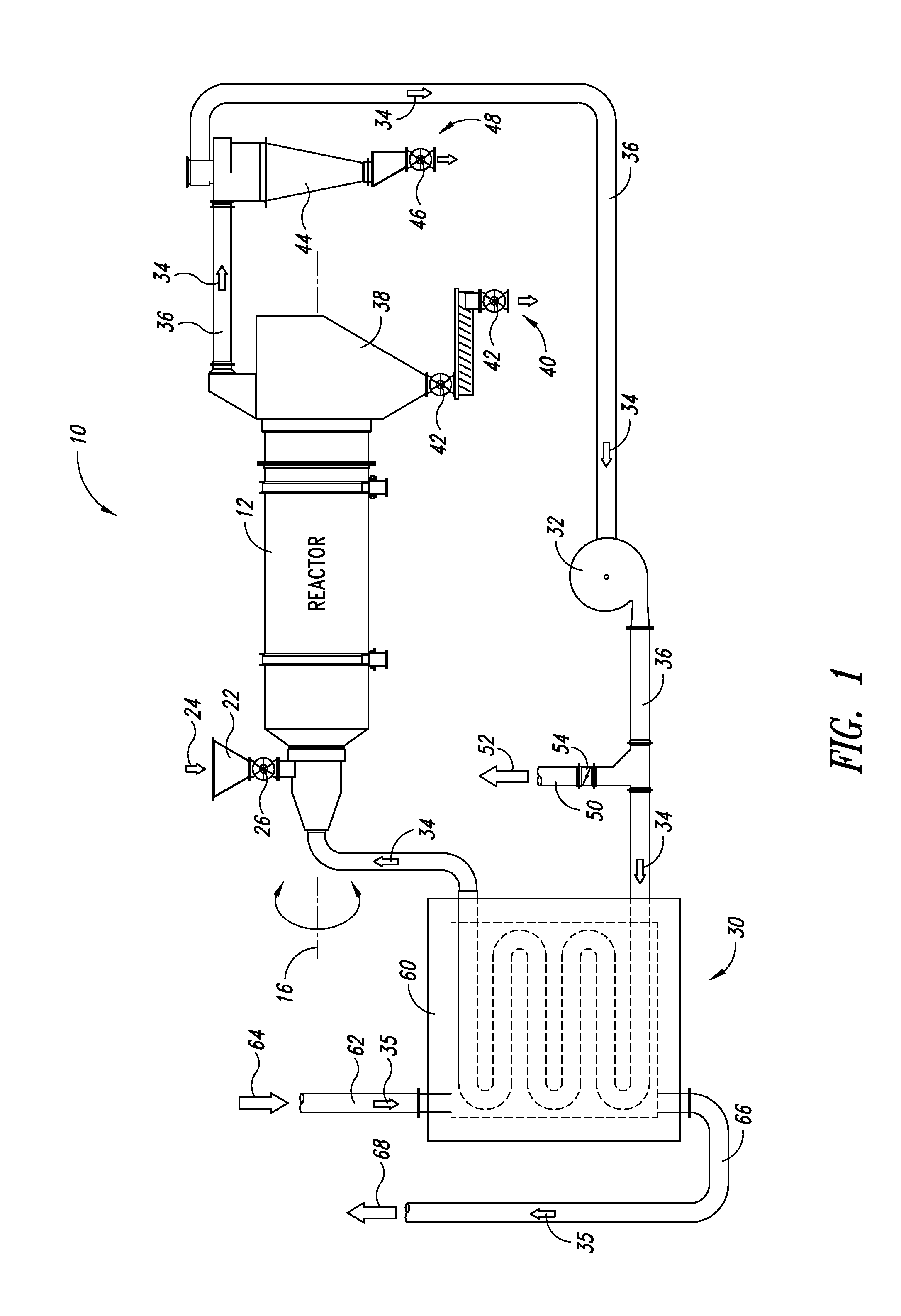
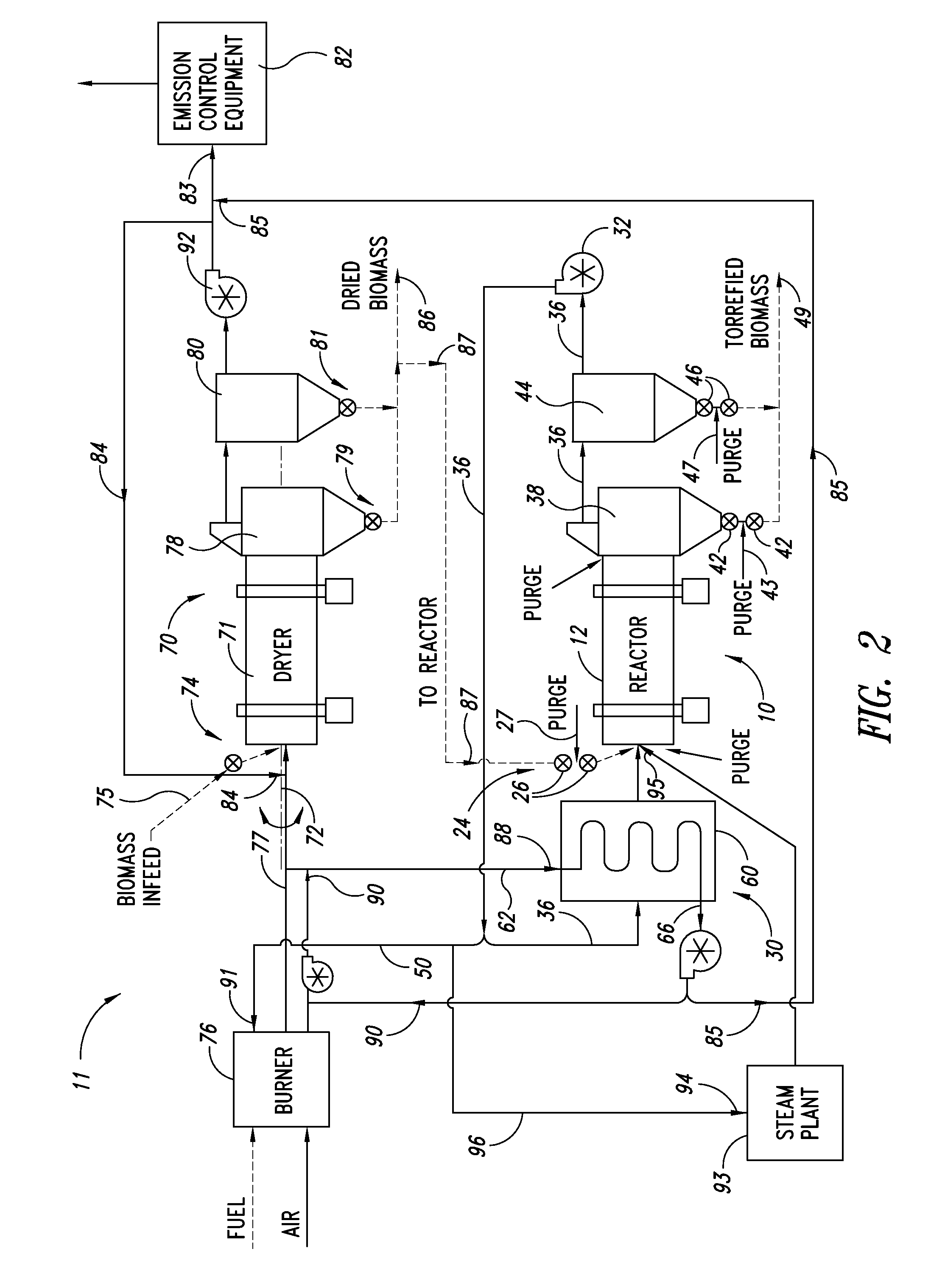
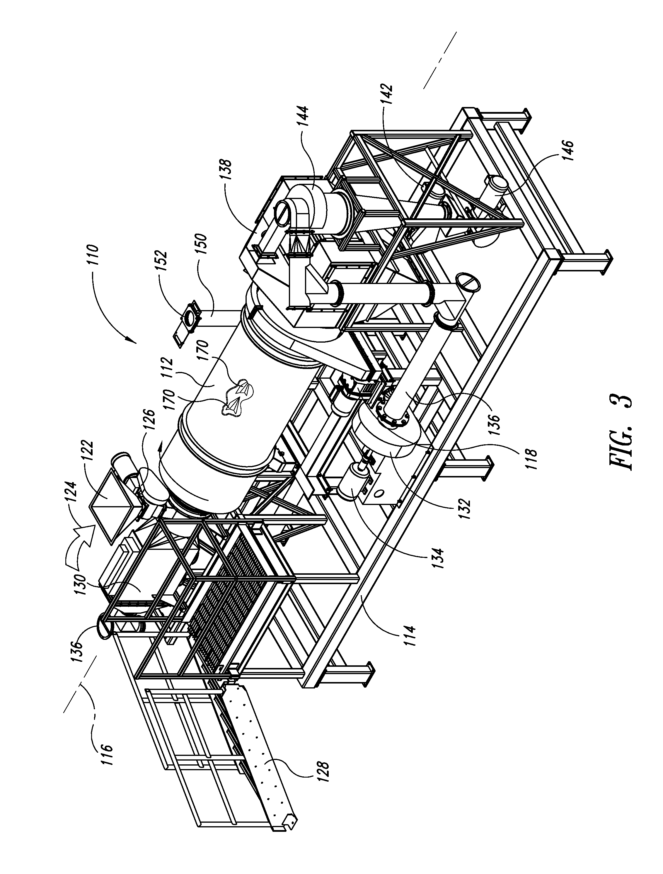
[0031]In the following description, certain specific details are set forth in order to provide a thorough understanding of various disclosed embodiments. However, one skilled in the relevant art will recognize that embodiments may be practiced without one or more of these specific details. In other instances, well-known structures or steps associated with industrial process equipment and industrial processes may not be shown or described in detail to avoid unnecessarily obscuring descriptions of the embodiments. For instance, it will be appreciated by those of ordinary skill in the relevant art that various sensors (e.g., temperature sensors, oxygen sensors, etc.), control devices and other industrial process controls may be provided and managed via a programmable logic controller (PLC) or other suitable control system for monitoring the biomass torrefaction systems described herein and controlling operational parameters of the torrefaction processes to optimize or tailor characteri...


PUM

PropertyMeasurementUnit
inlet temperatureaaaaaaaaaa
outlet temperatureaaaaaaaaaa

Abstract

A biomass torrefaction system is provided which enables a continuous torrefaction process that involves the introduction of biomass particles into a rotating reactor drum having a low oxygen environment. The particles are conveyed through the drum by a heated gas stream and simultaneously torrefied thereby. Gas exiting the drum is recirculated back to a heat source for reheating the gas prior to reentering the drum. A method of biomass torrefaction is also provided.

Description

CROSS-REFERENCE TO RELATED APPLICATION[0001]This application is a continuation application of U.S. application Ser. No. 13 / 218,230 filed Aug. 25, 2011, which claims the benefit under 35 U.S.C.§119(e) of U.S. Provisional Patent Application No. 61 / 391,442, filed Oct. 8, 2010, the entire disclosures of which are herein incorporated by reference for all purposes.BACKGROUND[0002]1. Technical Field[0003]This disclosure generally relates to biomass torrefaction systems and methods, including in particular cellulosic biomass torrefaction systems and methods.[0004]2. Description of the Related Art[0005]Torrefaction of biomass particles is well known and is a process in which biomass particles are heated in a low oxygen environment. This causes volatile compounds within the particles to be boiled off and the cellular structure of the particles to be degraded, resulting in a partial loss of mass and an increase in friability. It also causes a reaction within the remaining cellular structure th...

Claims


Application Information

Patent Timeline
Patent Type & Authority Applications(United States)
IPC IPC(8): C10L5/44
CPCC10B1/10C10B49/02C10B53/02C10L5/44C10L9/083F27B7/20C10B49/06F27D17/008Y02E50/10Y02E50/14Y02E50/15Y02E50/30F27D17/004F26B3/06F26B11/026F26B11/028F26B11/0486F26B21/001F26B21/002F26B21/004F26B21/04F26B21/10F26B21/12F26B25/00F26B25/002F26B25/005F26B25/04F26B25/16F26B25/22F26B2200/02F26B2200/08C10L9/08F27B7/16
Inventor TEAL, WILLIAM B.GOBEL, RICHARD J.JOHNSON, ANDREW
Owner TEAL SALES
Why Eureka
Try Eureka