

Integrated fcc biomass pyrolysis/upgrading
a biomass pyrolysis and biomass oil technology, applied in biofuels, hydrocarbon oil treatment products, biofuels, etc., can solve the problem of catalytic cracking of conventional fcc feed and risers
- Summary
- Abstract
- Description
- Claims
- Application Information
AI Technical Summary
Benefits of technology
Problems solved by technology
Method used
Image

Examples
example 1
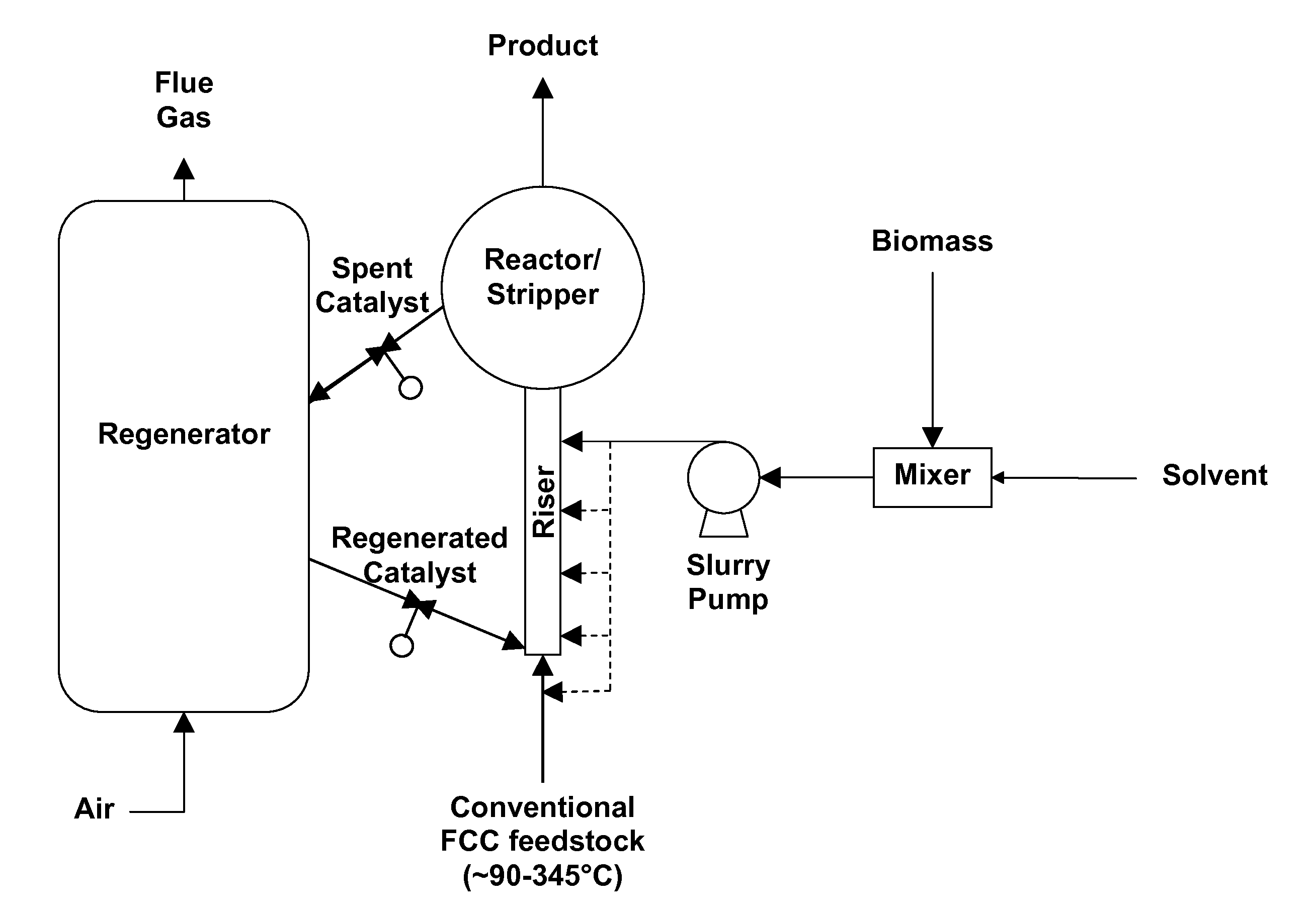
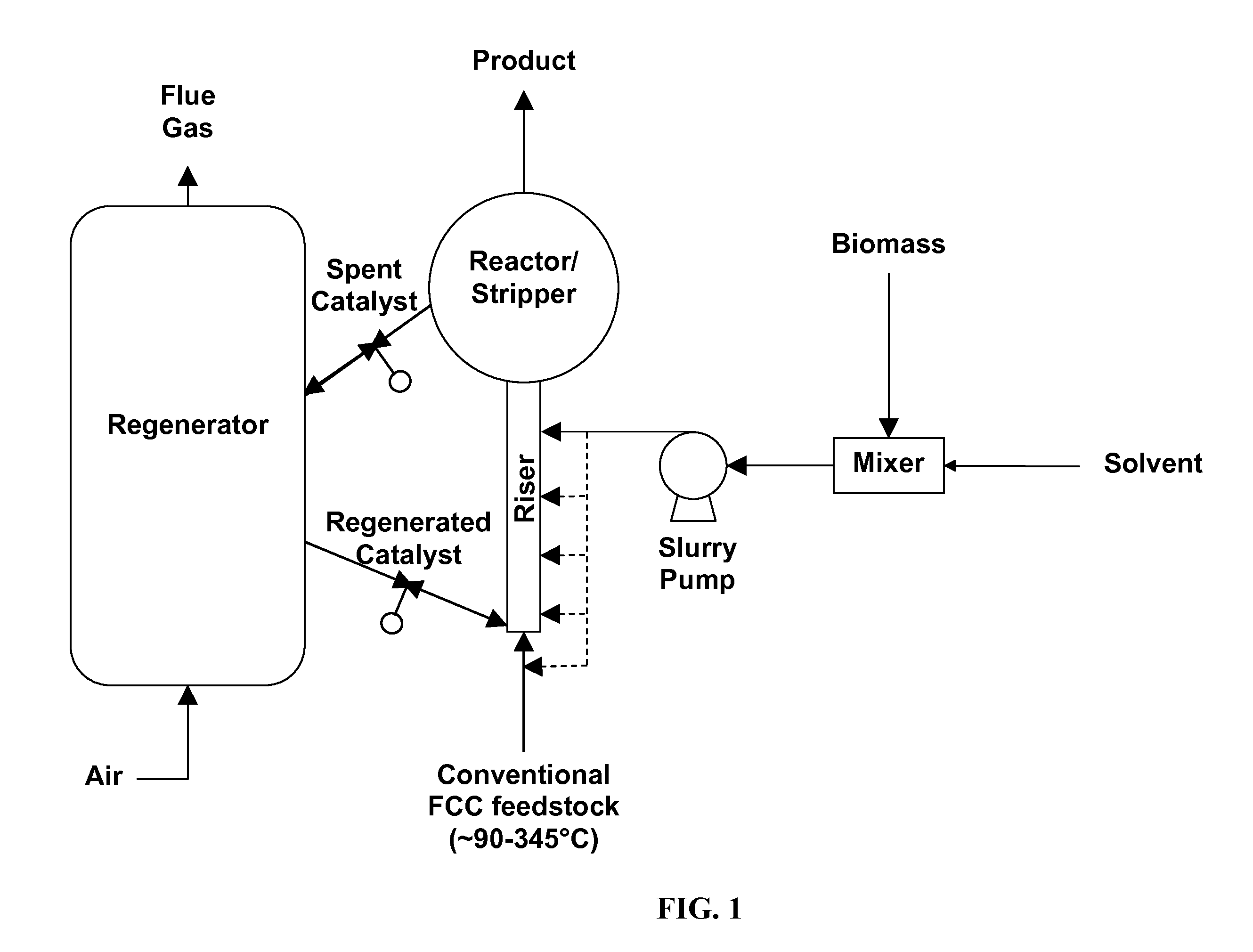
[0034]A slurry stream composed of (1) solid biomass particles and (2) conventional FCC feed is fed through a slurry pump into an FCC riser to achieve biomass pyrolysis and in situ pyrolysis oil upgrading. Another feed stream contains only conventional FCC feed stream is also injected into the riser for conventional catalytic cracking. The injection location for the mixed biomass feedstock could be located anywhere in the riser / reactor and may be altered dependent upon the characteristics of the biomass feed and the temperature of the recycled catalyst. For more difficult biomass materials the mixed biomass feed may be injected at low concentrations with the FCC feed stream at the base of the riser. This will allow small amounts of the biomass feedstock to be converted over longer periods of time to upgraded fuel products. For easier to upgrade biomass materials, higher concentrations of the mixed biomass feed may be injected at one or more injection points along the riser dependent ...
example 2
[0037]Reaction feasibility is assessed using an autoclave catalytic reactor. Feeds containing biomass, pyrolysis oil, conventional FCC feed streams and decant oil are fed into the catalytic reactor and measured across a variety of reaction temperatures, feed residence time, and catalyst to feed ratios. The reaction temperature, feed stream rates, feed residence time, biomass / solvent / conventional FCC feed concentrations, and FCC catalyst loadings are modified to obtain maximum fuel range products. The mixed feed stream may contain between 0.1 and 90% biomass (see TABLE 1).
TABLE 1Feed Composition for the FCCMixed feed streamConv. FCC feedBiomass (%)*% Solvent*% Conv. Feed110%10% Conv. FCC feed80%2 5%10% Conv. FCC feed,80%5% pyrolysis oil310%5% Conv. FCC feed,80%5% pyrolysis oil420%5% decant oil75%510%5% decant oil, 10%75%pyrolysis oil610%20% decant oil70%7 5%20% decant oil, 5%70%pyrolysis oil850%50% Conv. FCC feed0925%50% Conv. FCC feed,025% pyrolysis oil*% is final % w / v as determine...
example 3
[0038]Reaction conditions obtained in the autoclave catalytic reactor are revised to account for larger reaction beds and greater volumes in the ACE (Advanced Catalyst Evaluation) pilot scale tests. Minimal modulation of the feed residence time, biomass / solvent / conventional FCC feed ratios, catalyst to feed ratios, and reaction temperatures are required to obtain maximum amount of fuel range products. Once reaction rates and mechanism are determined, conditions are optimized for full scale refinery production. During ACE pilot scale tests, minimum and maximum concentrations of biomass are determined. This allows the full scale refinery to modulate biomass feed stream to maintain steady bio-fuel conversion and maximum upgraded fuel products.
[0039]Residence time may vary dependent upon injection point. Residence time is approximately 1 to 4 seconds from bottom of riser to top of the riser. When the injection is in the middle, residence time is approximately half of that from bottom of...
PUM
 Abstract
Description
Claims
Application Information