Control valve filter device

Active Publication Date: 2012-06-28
PIOLAX CO LTD
View PDF5 Cites 8 Cited by
  • Summary
  • Abstract
  • Description
  • Claims
  • Application Information

AI Technical Summary

Benefits of technology

[0011]According to the above configurations, the frame body is expanded and placed in a peripheral groove formed at an outer peripheral surface of a control valve, and the engagement claws are engaged with the concave portions of the frame body, thus allowing the filter device to be attached to the control valve. In this case, the concave portions with which the engagement claws are to be engaged are formed laterally of the openings of the frame body, and the engagement claws are engaged with the concave portions in these regions, thus making it p

Problems solved by technology

If foreign matter contained in fluid has intruded into su

Method used


Image

  • Control valve filter device
  • Control valve filter device
  • Control valve filter device

Examples


Example

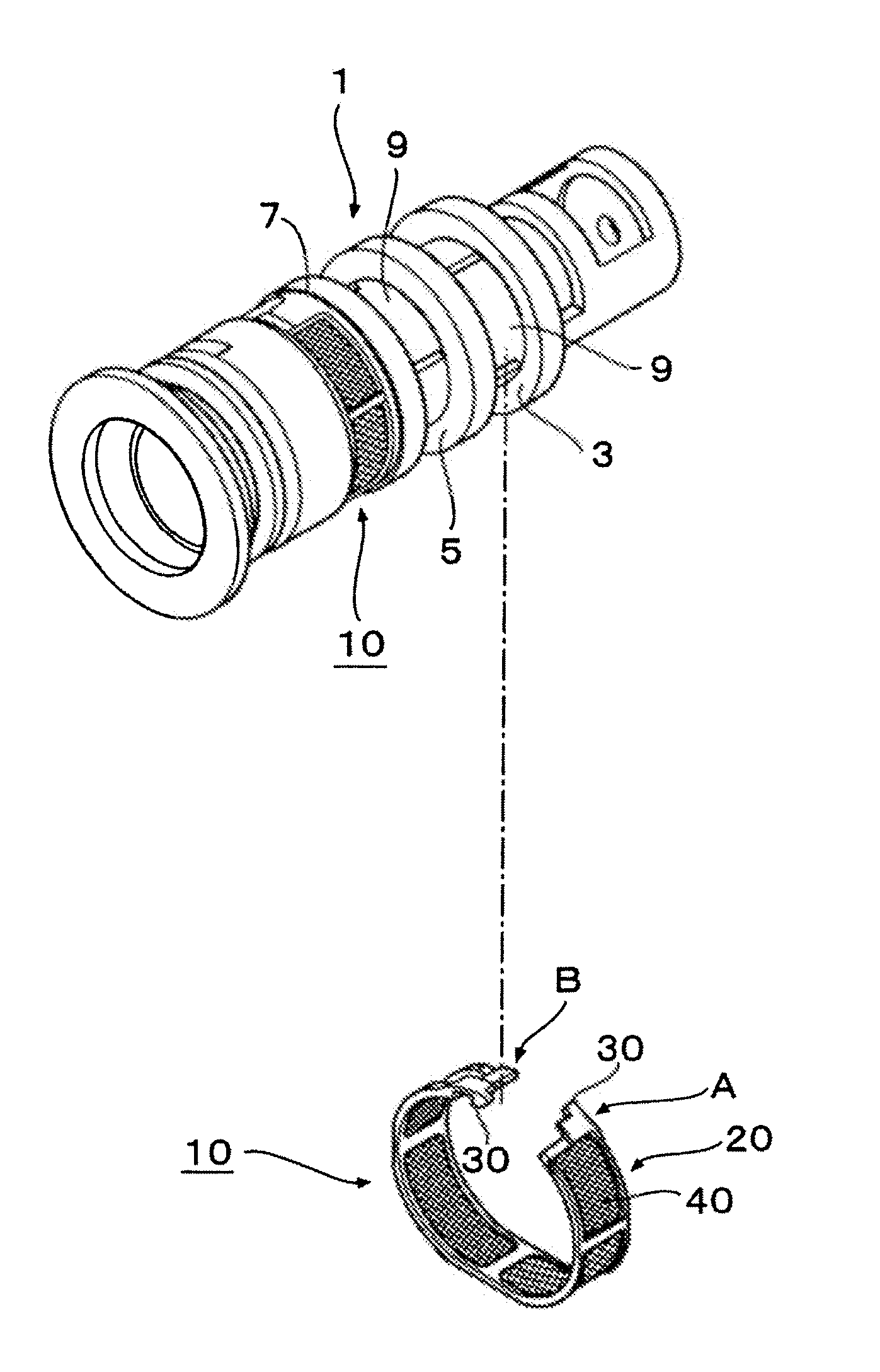
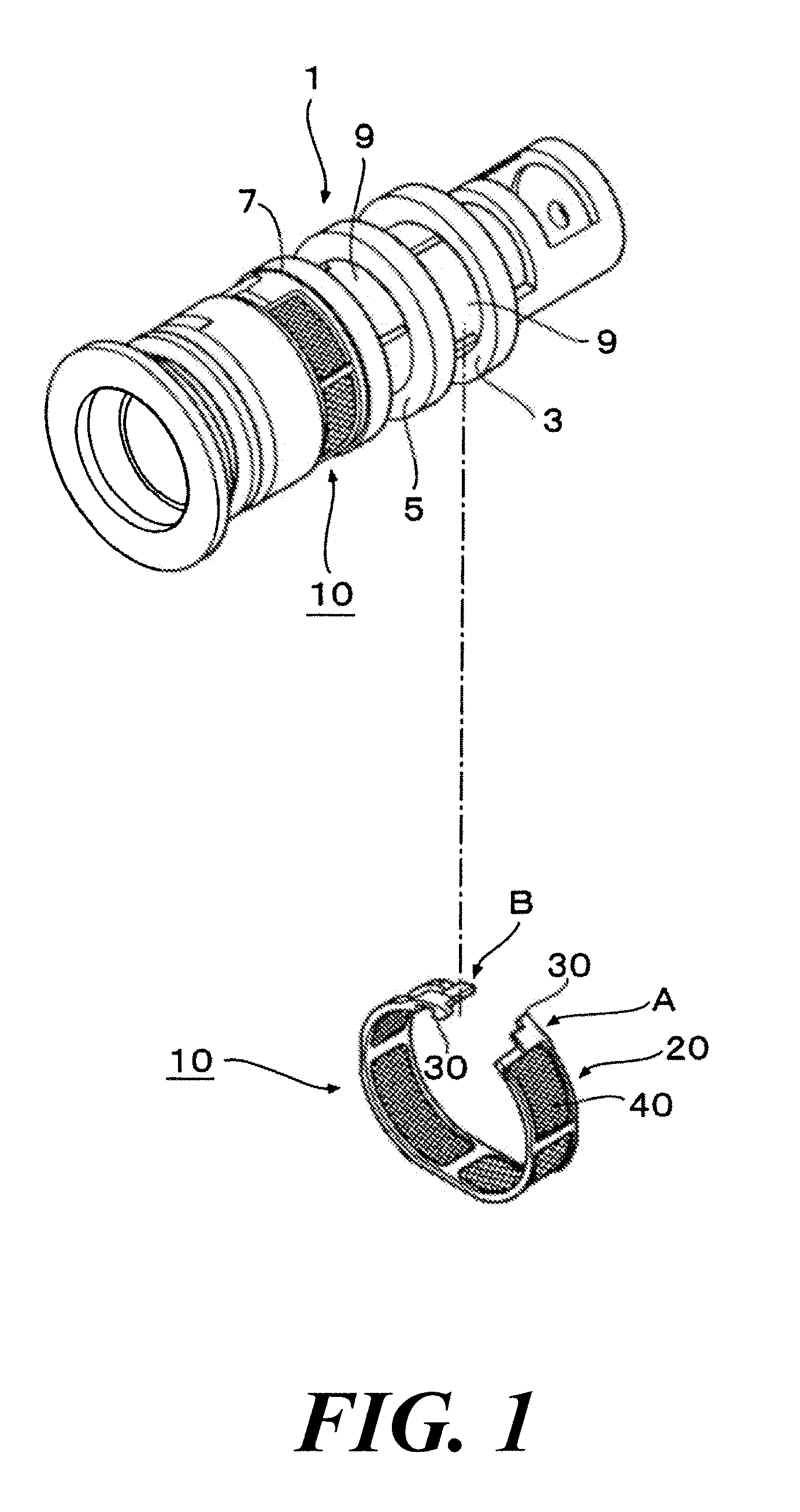
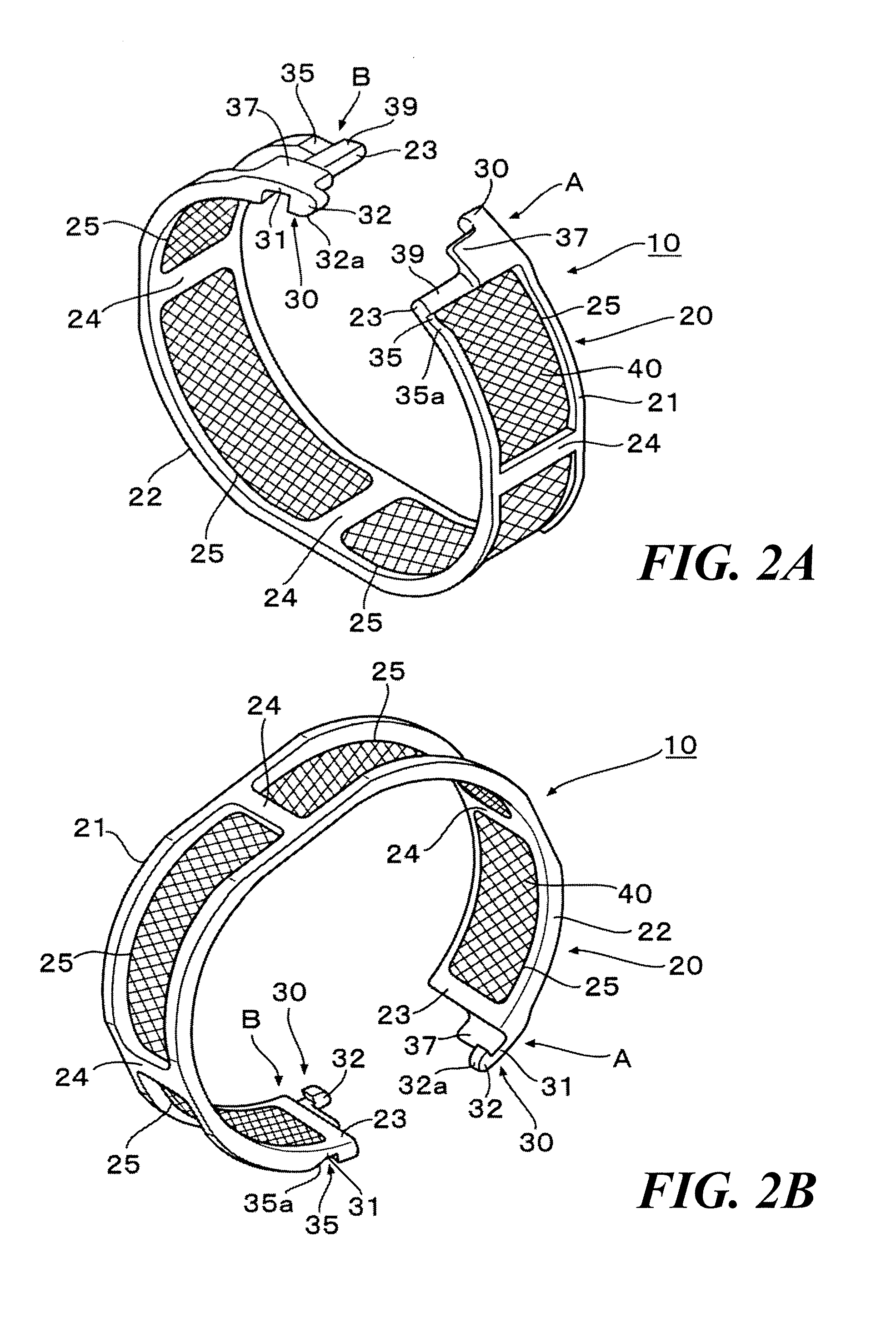
[0018]One embodiment of the control valve filter device will be described with reference to FIG. 1 to FIGS. 5A and 5B.

[0019]For example, a control valve 1 is provided in an oil hydraulic circuit of an automobile engine to change oil passage or perform pressure adjustment, or is provided in a fuel supply system to perform fuel injection amount adjustment, injection timing adjustment, etc. As illustrated in FIG. 1, a control valve filter device (filter device) 10 according to the embodiment is attached to the control valve 1. Plural peripheral grooves 3, 5 and 7 are formed on an outer periphery of the control valve 1 at given intervals along its axial direction. In this embodiment, the filter device 10 is attached to each of the peripheral grooves 3 and 7 located on both sides of the peripheral groove 5 in the axial direction. The peripheral grooves 3, 5 and 7 are each provided with a port part 9 communicated with the inside of the control valve 1.

[0020]As illustrated in FIG. 1 and FI...


PUM


Abstract

One embodiment provides a control valve filter device, including: a belt-like frame body curved into a ring shape so that its ends face each other, the frame body having an opening; a filter member provided in the opening of the frame body; an engagement claw extended from one of each of both corresponding lateral portions of the faced ends of the frame body; and a concave portion provided at the other of each of the both corresponding lateral portions of the faced ends of the frame body, so as to be engaged by the engagement claw, each concave portion being formed laterally of the opening of the frame body.

Description

CROSS-REFERENCE TO RELATED APPLICATION(S)[0001]This application claims priorities from Japanese Patent Application No. 2010-287741 filed on Dec. 24, 2010, the entire contents of which are incorporated herein by reference.FIELD[0002]The present invention relates to a control valve filter device that is attached to a control valve for controlling a fluid pressure or the like, and prevents intrusion of foreign matter into the control valve.BACKGROUND[0003]In an engine, an automatic transmission or the like of an automobile, for example, a control valve for controlling the pressure of fluid such as fuel or oil or for changing the passage of fuel or oil has been used in many cases. If foreign matter contained in fluid has intruded into such control valve, its normal operation might be inhibited. Thus, a filter is attached to such control valve for catching foreign matter contained in fluid.[0004]JP-2002-285966-A discloses a filter in which a frame body (53, the number in the brackets cor...

Claims


Application Information

Patent Timeline
IPC IPC(8): B01D35/02
CPCB01D2201/4084B01D29/112
Inventor KIMURA, TAKASHI
Owner PIOLAX CO LTD
Why Eureka
Try Eureka