Unlock instant, AI-driven research and patent intelligence for your innovation.

Light emitting diode package

Inactive Publication Date: 2012-06-28
ADVANCED OPTOELECTRONICS TECH
View PDF8 Cites 3 Cited by
  • Summary
  • Abstract
  • Description
  • Claims
  • Application Information

AI Technical Summary

Problems solved by technology

However, since the threshold voltages of the RGB light LED dies differ from each other, the required circuit to drive the LED dies is expensive and complicated.

Method used


Image

  • Light emitting diode package
  • Light emitting diode package
  • Light emitting diode package

Examples


Embodiment Construction

[0011]Reference will now be made to the drawings to describe the present LED package in detail.

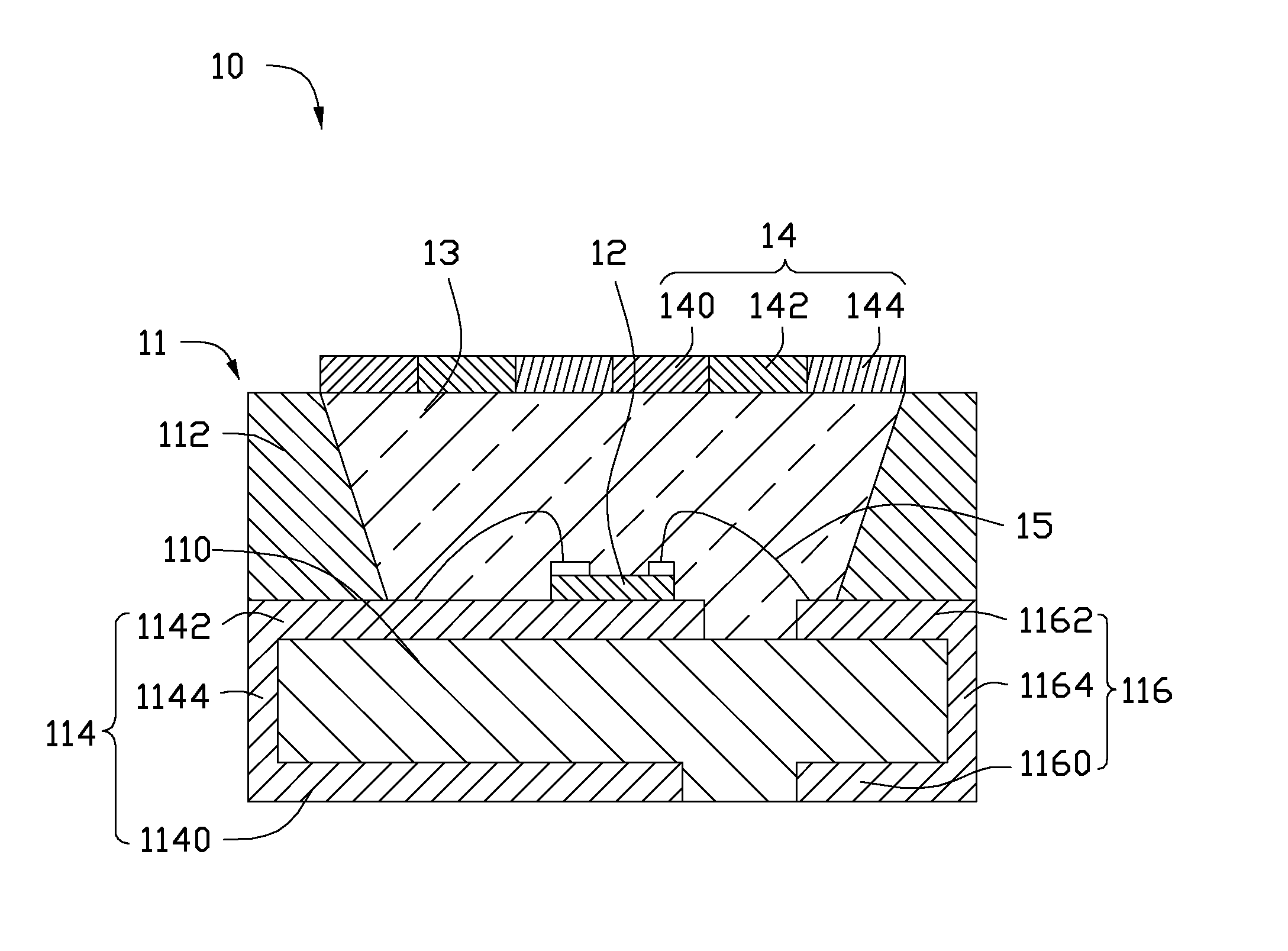
[0012]Referring to FIG. 1, an LED package 10 according to a first embodiment includes a base 11, an LED die 12, an encapsulation 13 and a light wavelength converting layer 14.

[0013]The base 11 includes a substrate 110, a reflective cup 112, a first electrode 114 and a second electrode 116. The first electrode 114 and the second electrode 116 are located on opposite lateral sides of the substrate 110. The reflective cup 112 is arranged on the first and second electrodes 114, 116.

[0014]The substrate 110 can be made integrally with the reflective cup 112. The substrate 110 can be made of silicon, plastic, ceramic or liquid crystal polymer. The reflective cup 112 can be made of liquid crystal polymer. The first electrode 114 and the second electrode 116 are made of metal. The first electrode 114 and the second electrode 116 are arranged at two side portions of the substrate 110. The first elec...


PUM


Abstract

An LED package includes a base, an LED die arranged on the base, an encapsulation sealing the LED die, and a light wavelength converting layer arranged on a light path of the LED die. The light wavelength converting layer includes a plurality of first areas comprising red fluorescent powder, a plurality of second areas comprising green fluorescent powder and a plurality of third areas comprising blue fluorescent powder. The first, second and third areas are aligned along a first direction and a second direction perpendicular to the first direction. Each two neighboring areas on the first direction have different colors. Each two neighboring areas on the second direction also have different colors.

Description

BACKGROUND[0001]1. Technical Field[0002]The present disclosure generally relates to light emitting diode (LED) packages.[0003]2. Description of Related Art[0004]White-light LED illuminating devices had been developed due to their light weight and low power consumption. Red, green and blue (RGB) LED dies can be combined in a common package to generate white light by mixing the tri-chromatic lights. However, since the threshold voltages of the RGB light LED dies differ from each other, the required circuit to drive the LED dies is expensive and complicated.[0005]Therefore, it is necessary to provide an LED package overcoming above shortcomings.BRIEF DESCRIPTION OF THE DRAWINGS[0006]Many aspects of the disclosure can be better understood with reference to the following drawings. The components in the drawings are not necessarily drawn to scale, the emphasis instead being placed upon clearly illustrating the principles of the disclosure.[0007]FIG. 1 is a schematic, cross-sectional view ...

Claims


Application Information

Patent Timeline
IPC IPC(8): H01L33/48H01L33/52
CPCH01L33/504H01L33/507H01L33/60H01L2224/48091H01L2224/48247H01L2924/00014
Inventor FANG, JUNG-HSIHSU, SHIH-YUAN
Owner ADVANCED OPTOELECTRONICS TECH
Features
  • R&D
  • Intellectual Property
  • Life Sciences
  • Materials
  • Tech Scout
  • Unparalleled Data Quality
  • Higher Quality Content
  • 60% Fewer Hallucinations
Learn More