Safety lanyard and manufacturing method thereof

a technology of safety lanyards and manufacturing methods, applied in the field of safety lanyards, can solve the problems that the known lanyards do not prove to be totally satisfactory, and achieve the effects of reducing the global space occupation of the lanyard in its rest position, large tension, and reducing the total distan

Inactive Publication Date: 2012-06-28
ZEDEL CORP
View PDF5 Cites 6 Cited by
  • Summary
  • Abstract
  • Description
  • Claims
  • Application Information

AI Technical Summary

Benefits of technology

[0007]Folding the elastic threads onto themselves so as to create bending zones enables the global space occupation of the lanyard in its rest position to be reduced. It can in fact easily be conceived that the total distance separating the two elements of this lanyard is then much smaller than the total length of the elastic threads. Under these conditions, the action of unfurling the lanyard enables this total distance to be considerably increased. Furthermore, this increase can be obtained without necessarily exerting a large tension on the lanyard, which is particularly favorable to its mechanical integrity and lifetime. Finally, the elastic nature of the threads enables the lanyard to be brought back naturally to its rest state, without using auxiliary equipment such as a winder.

Problems solved by technology

These known lanyards do not prove to be totally satisfactory, in particular on account of their relatively low elongation rate.

Method used


Image

  • Safety lanyard and manufacturing method thereof
  • Safety lanyard and manufacturing method thereof
  • Safety lanyard and manufacturing method thereof

Examples


Embodiment Construction

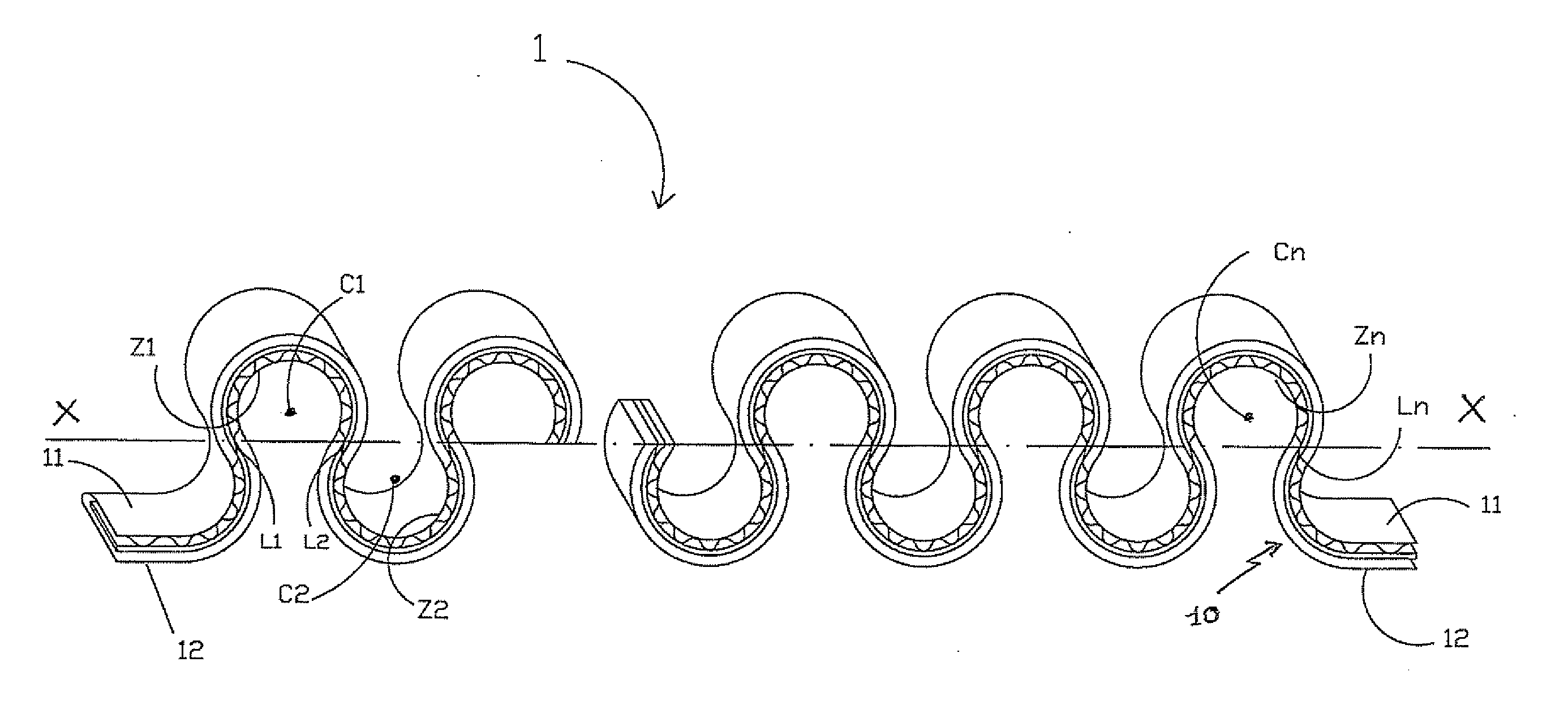
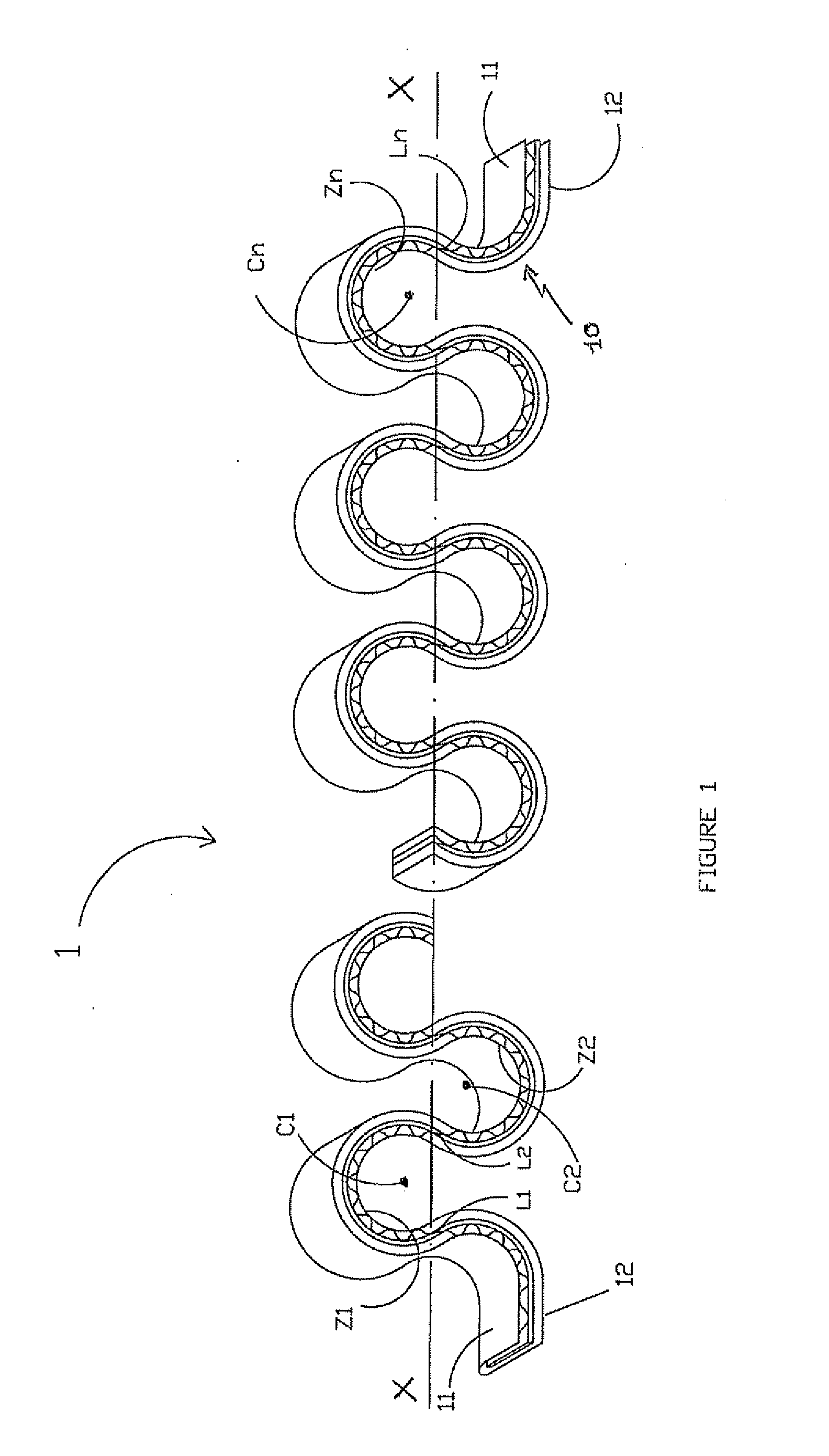
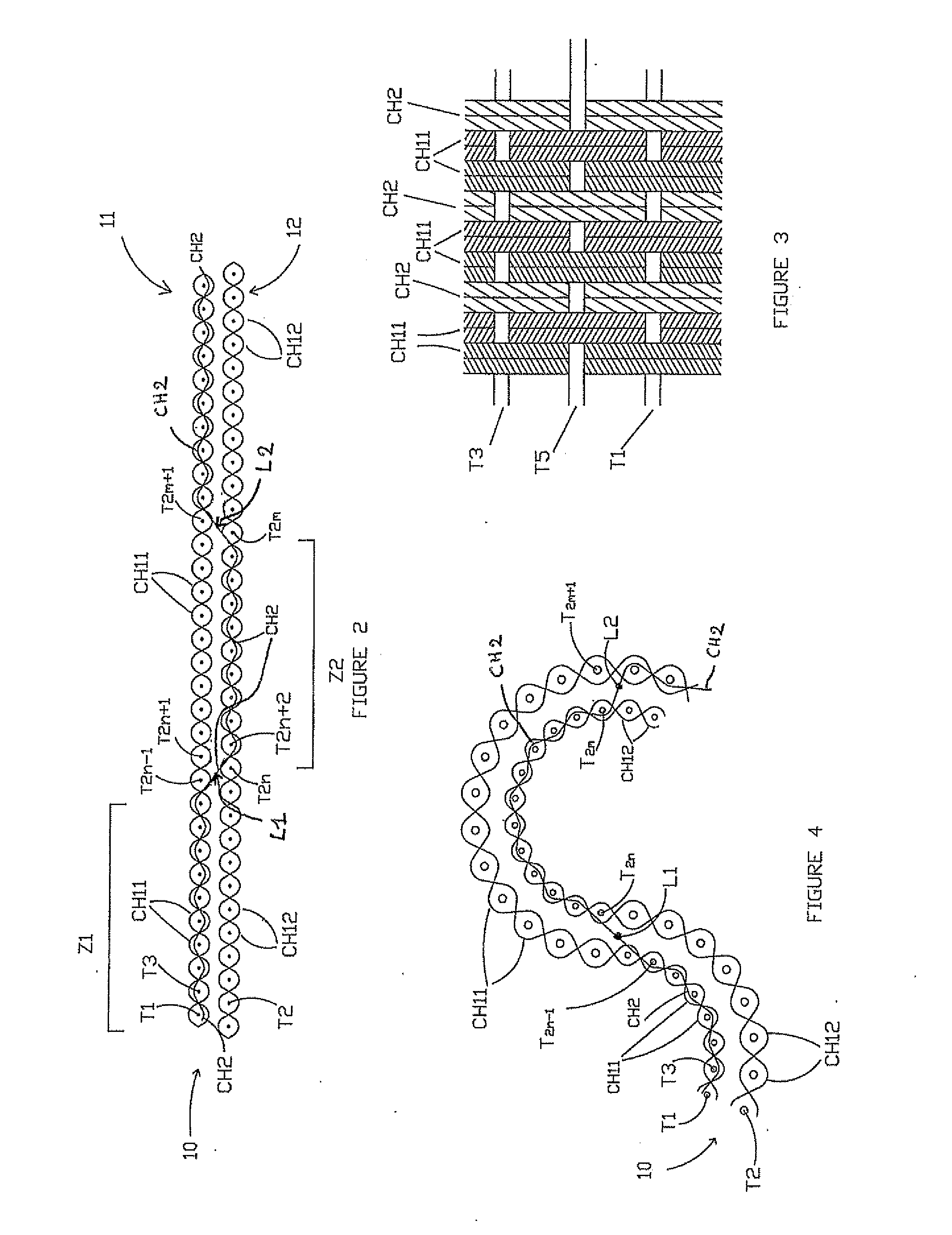
[0025]The lanyard 1 according to the invention, represented in partial manner in FIGS. 1 to 4, comprises a tubular sheath 10, essentially made from non-stretchable material, and a set of elastic threads described in greater detail in the following. The two opposite surfaces of this sheath, which presents a flattened shape, bear the reference numbers 11 and 12. The non-stretchable material, which is for example high-strength polyamide or polyester, has a very low elongation rate under normal conditions of use of the lanyard. This capacity is much lower than that of the elastic material constituting the threads, i.e. for example an elastomer such as latex or lycra™.

[0026]As shown in FIGS. 2 and 3, the sheath is woven from warp threads and weft threads. According to the invention, a majority of warp threads CH11 and CH12 made from non-stretchable material, designed to form the two surfaces 11 and 12, are first used. A certain proportion of elastic warp threads CH2, called link warp thr...


PUM

PropertyMeasurementUnit
angleaaaaaaaaaa
angleaaaaaaaaaa
elongationaaaaaaaaaa

Abstract

This lanyard, which is movable by elasticity between a rest position and a stretched position, comprises a tubular sheath made from non-stretchable material, and a set of elastic threads joined to the sheath.
According to the invention, the elastic threads define at least one longitudinal weaving zone in which they are woven on one surface of the sheath only, each weaving zone being proper to form a bending zone of the lanyard, in the rest position, in which the elastic threads are folded onto themselves.

Description

BACKGROUND OF THE INVENTION[0001]The invention relates to a safety lanyard, movable by elasticity between a rest position and a stretched position, comprising a tubular sheath made from non-stretchable material and a set of elastic threads secured to the sheath.STATE OF THE ART[0002]Lanyards formed by a flexible strip onto which a peripheral sheath is stitched are first of all known. In order to manufacture this first type of lanyards, the above-mentioned strip and sheath are first of all formed, in general by weaving, and this strip is then inserted in the stretched state into the sheath. These two elements are finally secured to one another by means of stitchings made at the two axial ends thereof. When the strip reverts to its rest state, it then deforms the sheath in the manner of a gusset.[0003]It is also known to weave certain threads with the two surfaces of the sheath, along a few weft threads. This enables transverse linking lines to be created, arranged regularly along the...

Claims


Application Information

Patent Timeline
Patent Type & Authority Applications(United States)
IPC IPC(8): A62B35/00F16F3/00D03D41/00D03D15/56
CPCA62B35/0075A62B35/04D03D3/005D03D15/08D03D3/08D03D11/02D03D13/00D03D3/02Y10T442/3179Y10T442/3024Y10T428/1362D03D15/56
Inventor HEDE, JEAN-MARC
Owner ZEDEL CORP
Why Eureka
Try Eureka