Power feeding device and contactless power feeding system provided with power feeding device

Inactive Publication Date: 2012-06-28
SEMICON ENERGY LAB CO LTD
View PDF3 Cites 33 Cited by
  • Summary
  • Abstract
  • Description
  • Claims
  • Application Information

AI Technical Summary

Benefits of technology

[0020]According to an embodiment of the present invention, a power feeding device utilizing an electromagnetic resonance coupling method and a contactless power feeding system provided with the power feeding device can be provided in which the coupling coefficient of electroma

Problems solved by technology

In improvement of transmission efficiency, an important factor is a coupling coefficient of electromagnetic resonance coupling between th

Method used


Image

  • Power feeding device and contactless power feeding system provided with power feeding device
  • Power feeding device and contactless power feeding system provided with power feeding device
  • Power feeding device and contactless power feeding system provided with power feeding device

Examples


embodiment 1

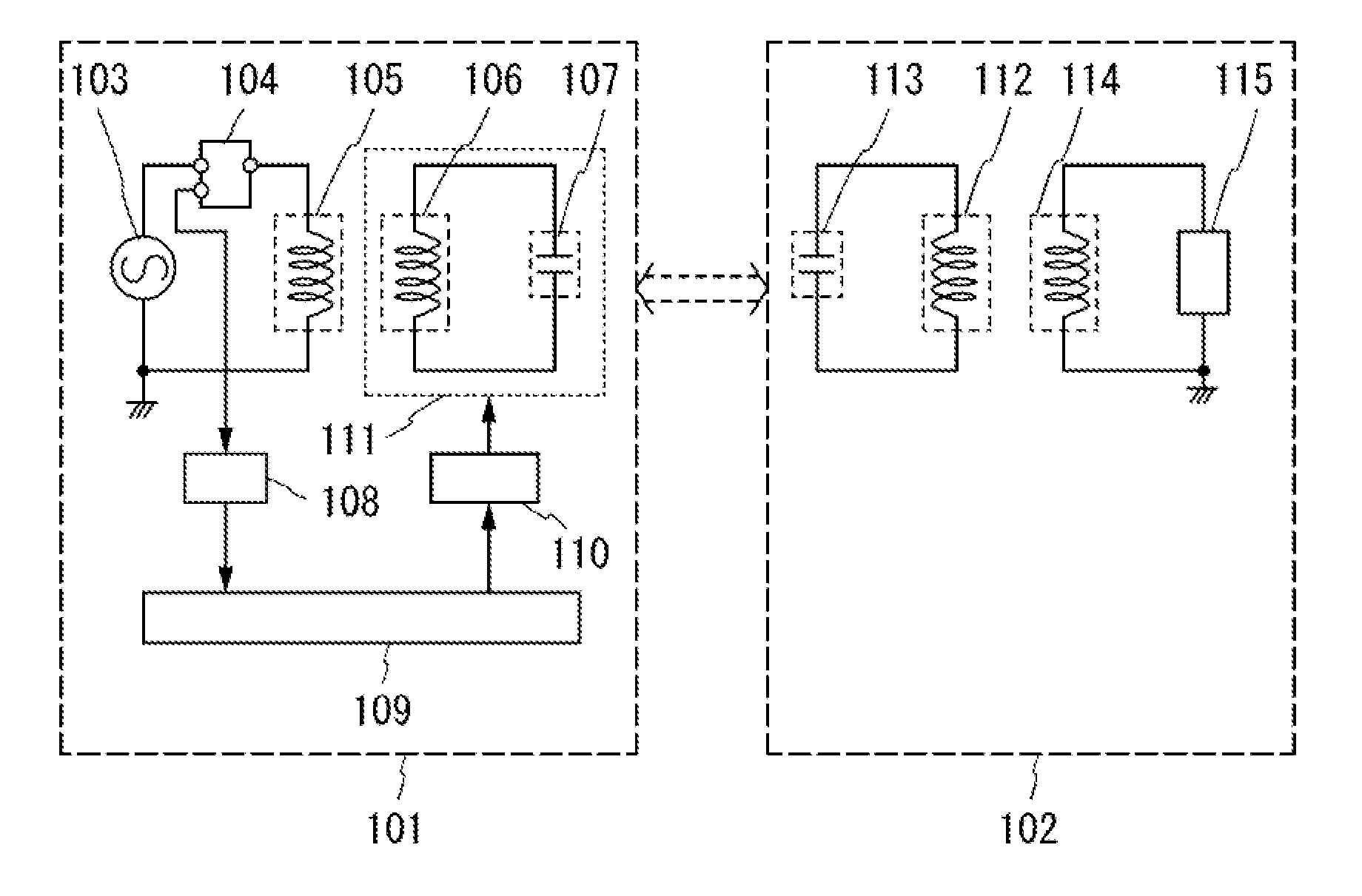
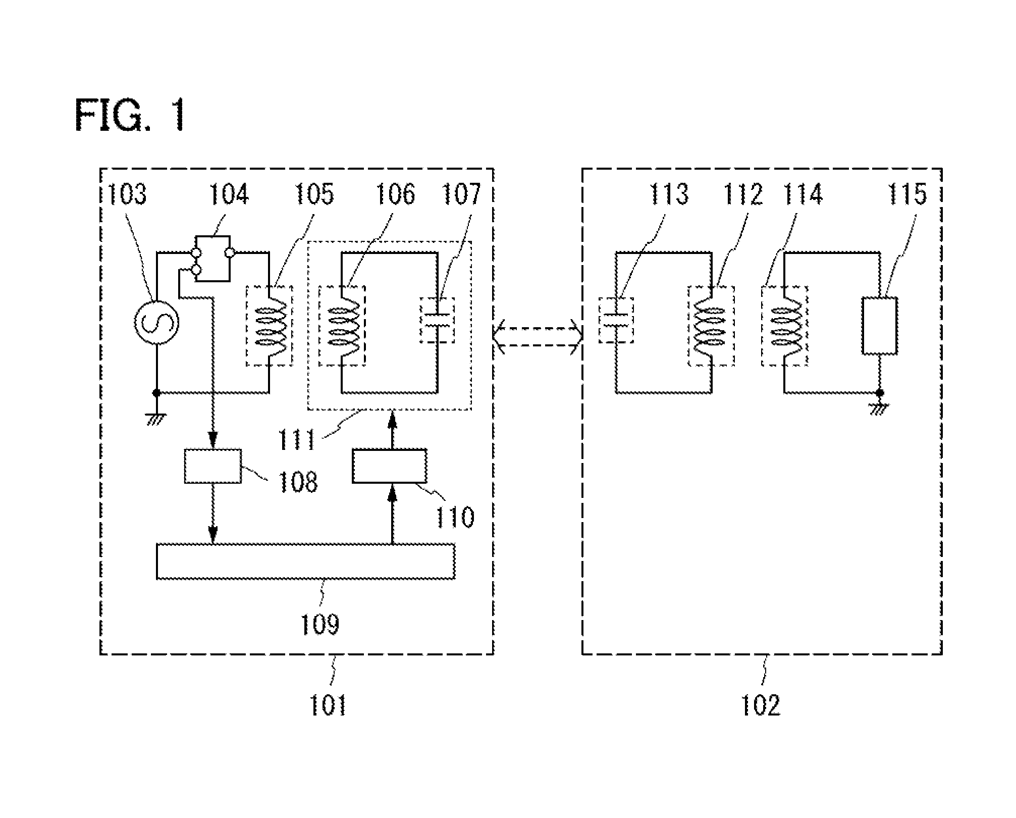
[0035]In this embodiment, a power feeding device which performs contactless power feeding utilizing an electromagnetic resonance method and a contactless power feeding system utilizing the electromagnetic resonance method, which are an embodiment of the present invention, will be described. Specifically, in order to minimize a reflection component of electric power output from a high-frequency power source of the power feeding device, a position (d) of a first resonant coil 106 or a first resonant circuit 111 of a power feeding device 101 is transferred on the basis plan, S11 parameter showing a reflection component. Note that to minimize the S11 parameter showing a reflection component means to maximize the S21 parameter showing transmission efficiency.

[0036]FIG. 1 illustrates a block diagram of the power feeding device 101 and a power receiving device 102. Note that the power feeding device 101 can transmit electric power to the power receiving device 102 without contact by resona...

embodiment 2

[0061]In this embodiment, a power feeding device which performs contactless power feeding utilizing the electromagnetic resonance method and a contactless power feeding system utilizing the electromagnetic resonance method, which are an embodiment of the present invention, will be described. Specifically, in order to minimize a reflection component of electric power output from a high-frequency power source of the power feeding device, a position (d) of a first resonant coil 106 or a first resonant circuit 111 of a power feeding device 101, and the second resonant coil 112 of the power receiving device 102 or a position (d) of a second resonant circuit 116, are transferred on the basis Of an S11 parameter showing a reflection component. Note that to minimize the S11 parameter showing a reflection component means to maximize the S21 parameter showing transmission efficiency.

[0062]FIG. 6 illustrates a block diagram of the newer feeding device 101 and the power receiving device 102. No...

embodiment 3

[0083]In this embodiment, application of the contactless power feeding system explained in the above embodiments will be described. Note that examples of the application of the contactless power feeding system of the present invention are a portable telephone, a digital video camera, a computer, a portable information terminal (such as a mobile computer, a portable telephone, a portable game machine, or an electronic book), and an image reproduction device including a recording medium (specifically, a digital versatile disc, or ‘DVD’), which are portable electronic devices; a household electrical appliance such as a rice cooker, a television, or refrigerator; and an electric propulsion mobile unit which is driven by using electric power, such as an electric car, and the like. Examples thereof will be described with reference to drawings below.

[0084]FIG. 11A illustrates an example in which a mobile phone and a portable information terminal are given as applications of the contactless...


PUM


Abstract

A power feeding device utilizing an electromagnetic resonance coupling method and a contactless power feeding system can be provided. A coupling coefficient of electromagnetic induction coupling in the power feeding device and/or the inside of a power receiving device is optimized to improve electric power transmission efficiency of a resonance frequency regardless of positions of the power feeding device and the power receiving device. Provided is a power feeding device or a contactless power feeding system in which an S11 parameter which is a reflection component of electric power output from a high-frequency power source of the power feeding device is monitored, and one or both of positions of a transmission coil and a first resonant coil in the power feeding device and positions of a reception coil and a second resonant coil in a power receiving device are changed to adjust a coupling coefficient of electromagnetic induction coupling.

Description

BACKGROUND OF THE INVENTION[0001]1. Field of the Invention[0002]The present invention relates to a power feeding device and a contactless power feeding system provided with the power feeding device.[0003]2. Description of the Related Art[0004]In recent years, various kinds of electronic devices have been spread and various products have been on the market. In recent years, while spread of a portable electronic device, such as a mobile phone and a digital video camera, is noticeable, a electric vehicle which is driven by electric power, such as an electric car and a hybrid car, begins to appear, on the market.[0005]Such an electronic device and a electric vehicle usually include a battery as a storage means. For now, a power feeding method for charging the battery is direct contact between a household alternating current power supply and the battery.[0006]On the other hand, a power feeding method in which a battery is charged without contact has been researched and developed. Example...

Claims


Application Information

Patent Timeline
IPC IPC(8): H02J17/00
CPCH01F27/006H02J5/005H01F38/14H02J50/12H02J50/80H02J50/502H02J50/90H02J50/40
Inventor KAMATA, KOICHIRO
Owner SEMICON ENERGY LAB CO LTD
Why Eureka
Try Eureka