Controller

a technology of control board and electric motor, which is applied in the direction of motor/generator/converter stopper, dynamo-electric converter control, instruments, etc., can solve the problems of increasing the load of the vehicle driver for the steering operation, the driver's feeling for the steering operation may be decreased, and the electric motor's rotational balance becomes worse, so as to achieve the effect of improving the rotational balance of the electric motor, simplifying the structure of the wiring pattern on the control

Active Publication Date: 2012-06-28
DENSO CORP
View PDF5 Cites 28 Cited by
  • Summary
  • Abstract
  • Description
  • Claims
  • Application Information

AI Technical Summary

Benefits of technology

[0007]The present invention is made in view of the above problems. It is an object of the present invention to provide a controller, according to which the rotational balance of the electric motor is increased.
[0013]According to the above feature of the invention, a length of the wiring patterns between the micro-computer and the first pre-driver circuit can be easily made equal to a length of the wiring patterns between the micro-computer 94 and the second pre-driver circuit. In other words, the impedance from the micro-computer to the first pre-driver circuit and the impedance from the micro-computer to the second pre-driver circuit can be easily made equivalent to each other.
[0014]In addition, a length of the wiring patterns between the first pre-driver circuit and the first current-supply circuit can be easily made equal to a length of the wiring patterns between the second pre-driver circuit and the second current-supply circuit. In other words, the impedance between the first pre-driver circuit and the first current-supply circuit and the impedance between the second pre-driver circuit and the second current-supply circuit can be easily made equivalent to each other.
[0015]As a result, the impedance from the micro-computer to the first current-supply circuit and the impedance from the micro-computer to the second current-supply circuit can be easily made equivalent to each other. Therefore, the driving current to be supplied from the first current-supply circuit to the electric motor can be easily made equal to the driving current to be supplied from the second current-supply circuit to the electric motor. The rotational balance of the electric motor can be thereby improved.
[0016]In addition, according to the present embodiment, the wiring patterns for connecting the output terminals of the micro-computer to the input terminals of the first pre-driver circuit and the wiring patterns for connecting the output terminals of the micro-computer to the input terminals of the second pre-driver circuit can be formed on the circuit board without intersecting with each other. In a similar manner, the wiring patterns for connecting the output terminals of the first pre-driver circuit to the first current-supply circuit and the wiring patterns for connecting the output terminals of the second pre-driver circuit to the second current-supply circuit can be formed on the circuit board without intersecting with each other. Accordingly, a structure for the wiring patterns on the control board can be simplified and cross-talk can be suppressed.

Problems solved by technology

Therefore, in a case that the inverter circuit breaks down, a load to the vehicle driver for the steering operation is increased.
However, when a difference exists between a value of driving current supplied to the electric motor from one of the inverter circuits and a value of driving current supplied to the electric motor from the other of the inverter circuits, a rotational balance of the electric motor becomes worse and driver's feeling for the steering operation may be decreased.

Method used


Image

  • Controller
  • Controller
  • Controller

Examples


first embodiment

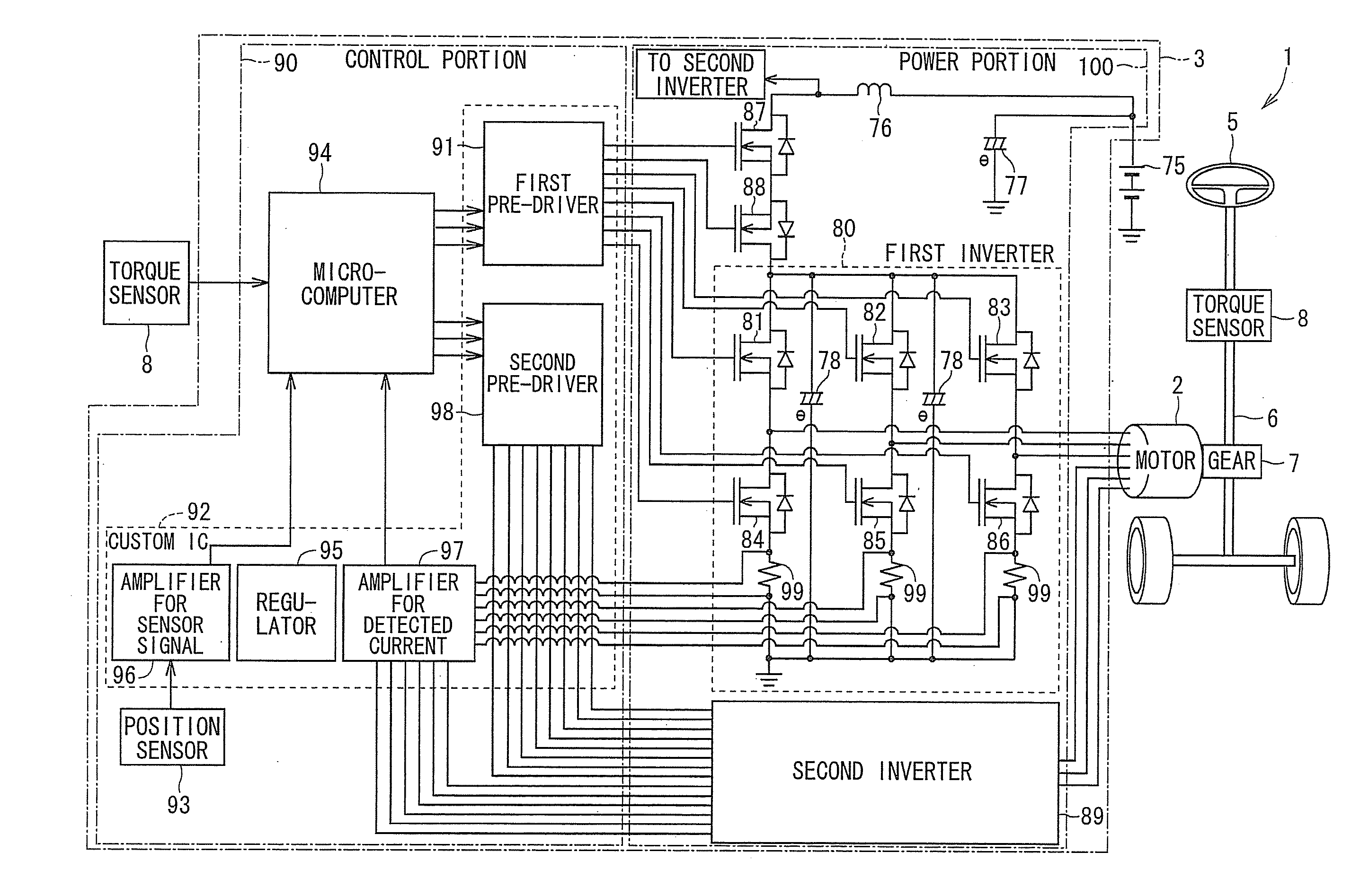
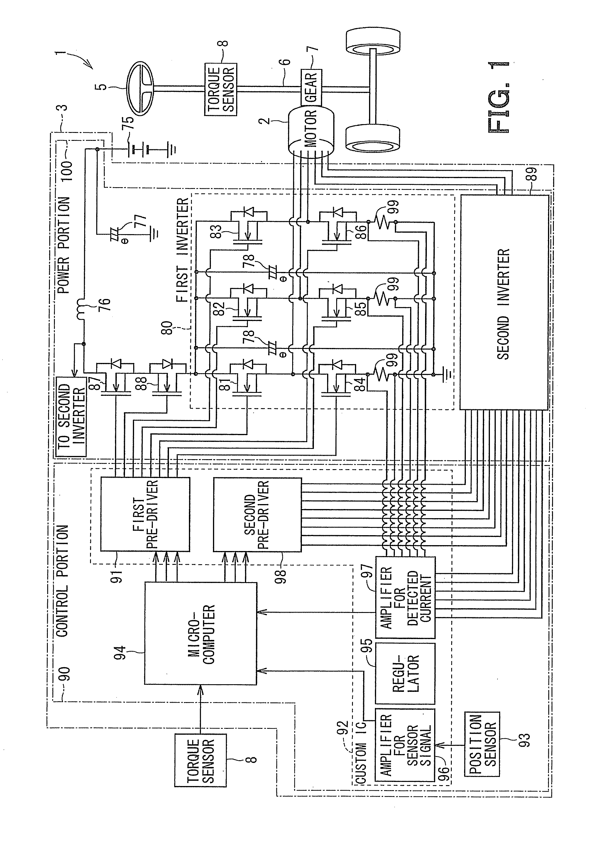
[0028]A driving apparatus 1, to which a controller 3 according to a first embodiment of the present invention is applied, is shown in FIGS. 1 to 8. The controller 3 of the present embodiment drives and controls an operation (rotation) of an electric motor 2 of the driving apparatus 1, which is applied to an electrical power steering device (EPS) for a vehicle. As shown in FIG. 1, the electric motor 2 of the driving apparatus 1 is engaged with a gear of a gear box 7 provided in a column shaft 6. The electric motor 2 of the driving apparatus 1 is rotated in a forward direction or in a backward direction depending on a torque signal outputted from a torque sensor 8 which detects a steering torque of a steering wheel 5 and a vehicle speed signal obtained from CAN (a Controller Area Network: not shown), so as to generate an assisting power for the steering operation.

[0029]The driving apparatus 1 is composed of the electric motor 2 and the controller 3. The electric motor 2 is a brushless...

second embodiment

[0106]FIG. 9 shows the control board 40 for the controller according to a second embodiment of the present invention. The same reference numerals are used in the second embodiment for the purpose of designating the same or similar part or portion to the first embodiment, to thereby omit repeated explanation as much as possible. According to the present embodiment, the custom IC is composed of a first custom IC 921 and a second custom IC 922. The first custom IC 921 has the first pre-driver circuit 91, while the second custom IC 922 has the second pre-driver circuit 98. The first and second custom ICs 921 and 922 are arranged on the control board 40 so as to be symmetric with respect to the center line S.

[0107]The input terminals 103, through which the operation signals are inputted from the micro-computer 94 into the first pre-driver circuit 91, are provided in the first custom IC 921 on a side to the second custom IC 922. The output terminals 105 for outputting the control signals ...


PUM


Abstract

Each of a first and a second inverter circuit supplies a driving current to an electric motor in a different power supply line. A custom IC has a first pre-driver circuit for outputting control signals to the first inverter circuit and a second pre-driver circuit for outputting control signals to the second inverter circuit. A micro-computer for outputting operation signals to the first and second pre-driver circuits is mounted to a control board on a center line. A distance between the center line and the first inverter circuit and a distance between the center line and the second inverter circuit is equal to each other. First and second output terminals of the micro-computer as well as first and second input and output terminals of the custom IC are symmetric with respect to the center line.

Description

CROSS REFERENCE TO RELATED APPLICATION[0001]This application is based on Japanese Patent Application No. 2010-292293 filed on Dec. 28, 2010, the disclosure of which is incorporated herein by reference.FIELD OF THE INVENTION[0002]The present invention relates to a controller for driving and controlling an operation of an electric motor.BACKGROUND OF THE INVENTION[0003]In an electric driving apparatus, which is applied to an electrical power steering system of a vehicle for assisting a steering operation of a vehicle driver, it is known in the art that an electric motor and a controller for driving and controlling the electric motor are combined into one, for example, as disclosed in Japanese Patent Publication No. 2002-120739.[0004]According to the above controller, the electric motor is operated by a single system of an inverter circuit. Therefore, in a case that the inverter circuit breaks down, a load to the vehicle driver for the steering operation is increased.[0005]In a case th...

Claims


Application Information

Patent Timeline
Patent Type & Authority Applications(United States)
IPC IPC(8): H02P25/22G06F1/18H02M7/48H02P29/00
CPCB62D5/0406B62D5/0484H02P2201/07H02K11/0073H02P25/22H02K5/225H02K11/33
Inventor YAMASAKI, MASASHI
Owner DENSO CORP
Why Eureka
Try Eureka