Electrical load driving apparatus

a technology of electric load and driving apparatus, which is applied in the direction of pulse generators, pulse techniques, instruments, etc., can solve the problems of over conventional electrical load driving apparatus reliability disadvantage and rapid deformation of current supply transistors, and achieve the effect of placing a large current burden

Active Publication Date: 2012-06-28
DENSO CORP
View PDF3 Cites 14 Cited by
  • Summary
  • Abstract
  • Description
  • Claims
  • Application Information

AI Technical Summary

Benefits of technology

[0016]According to the exemplary embodiment, there is provided an electrical load driving apparatus including a plurality of current supply transistors connected in parallel with one another to supply a current to an electrical load, and capable of detecting wire breakage in a plurality of current supply wires, in each of which a corresponding one of the current supply transistors is interposed, without placing a large current burden on the current supply transistors and without interrupting current supply to the electrical load.

Problems solved by technology

However, the above conventional electrical load driving apparatus has a disadvantage in reliability, because the sole-on period is generated within the current supply period.
More specifically, in a case where the electrical load is not a load that should be driven only a short period in response to a certain event, but a load that should be drive continuously (for example a relay for relaying power to an ignition system of a vehicle), since the failure detection is performed by turning on one of the current supply transistors during each sole-on period all the while the vehicle is running, the current supply transistors may degrade quickly.

Method used


Image

  • Electrical load driving apparatus
  • Electrical load driving apparatus
  • Electrical load driving apparatus

Examples


Embodiment Construction

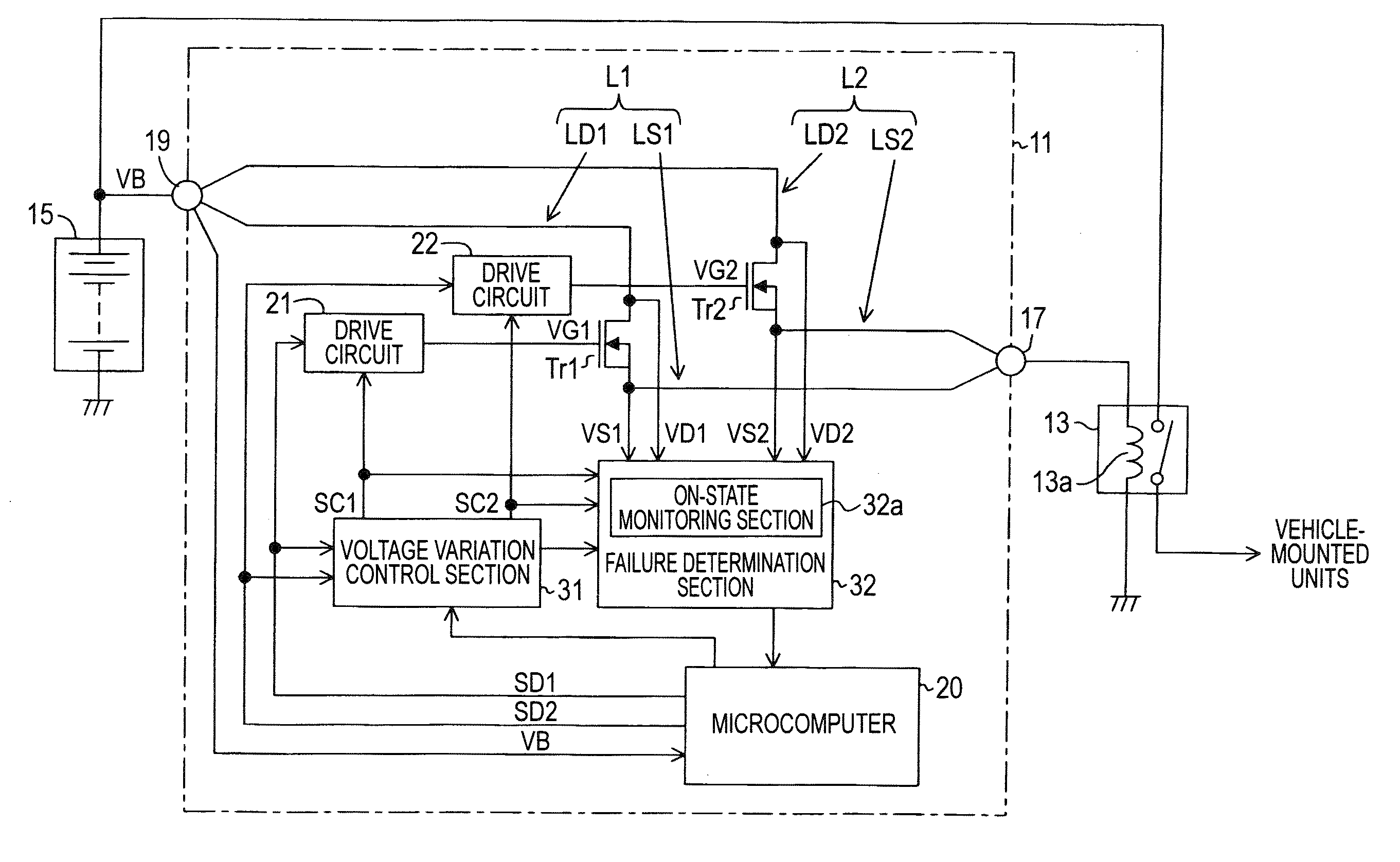
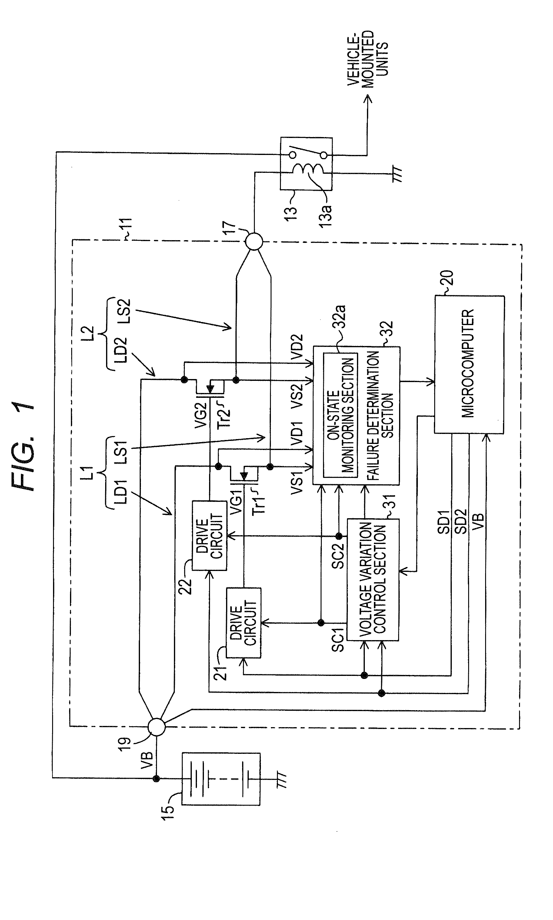
[0024]FIG. 1 is a diagram showing the structure of an ECU 11 as an electrical load driving apparatus according to a first embodiment of the invention.

[0025]The ECU 11 is mounted on a vehicle to turn on and off a relay 13 mounted on a vehicle by passing a current to a coil 13a of the relay 13. When the relay 13 is turned on, a battery voltage VB of a battery 15 is supplied to various vehicle-mounted units and devices related to the ignition system of the vehicle as a power supply voltage. More specifically, the ECU 11 turns on the relay 13 when a vehicle driver operates the ignition switch of the vehicle to supply the battery voltage VB to the various vehicle-mounted units and devices, and turns off the relay 13 when the vehicle driver turns off the ignition switch on condition that a predetermined power supply stop condition is satisfied.

[0026]In this embodiment, the relay coil 13a of the relay 13 is high side driven by the ECU 11. Accordingly, one end of the relay coil 13a is conne...


PUM


Abstract

The electrical load driving apparatus includes means for alternately lowering the gate voltages of two current supply transistors connected in parallel to each other at regular time intervals, a current being supplied to an electrical load through drain-source paths of both the current supply transistors, and means for detecting wire breakage in two current supply wires in which the current supply transistors are interposed respectively at portions opposite the electrical load with respect to the current supply transistors based on the drain-source voltages of the current supply transistors.

Description

[0001]This application claims priority to Japanese Patent Application No. 2010-290904 filed on Dec. 27, 2010, the entire contents of which are hereby incorporated by reference.BACKGROUND OF THE INVENTION[0002]1. Field of the Invention[0003]The present invention relates to an electrical load driving apparatus for supplying a current to an electrical load through a plurality of transistors.[0004]2. Description of Related Art Japanese Patent Application Laid-open number 2003-158447 discloses such an electrical load driving apparatus having a structure in which a plurality of power supply wires are connected in parallel, one connection node of the power supply wires being connected to one end of an electrical load which is connected to one of the high voltage side and the low voltage side of a power source, the other node being connected to the other of the high voltage side and the low voltage side of the power source, and each of the power supply wires including a current supply trans...

Claims


Application Information

Patent Timeline
Patent Type & Authority Applications(United States)
IPC IPC(8): H03K3/00G01R31/58
CPCG01R31/026G01R31/006G01R31/54G01R31/52G01R31/58
Inventor KANAYAMA, MITSUHIRO
Owner DENSO CORP
Why Eureka
Try Eureka