Cleaning blade for electrophotographic apparatus, and method for producing the same

a cleaning blade and electrophotography technology, applied in the direction of instruments, synthetic resin layered products, transportation and packaging, etc., can solve the problems of easy wear or damage increase the friction between the blade member and the methods described below, so as to improve the slip properties of the image bearing member, improve the cleaning effect, and improve the hardness

Active Publication Date: 2012-06-28
CANON KK
View PDF2 Cites 11 Cited by
  • Summary
  • Abstract
  • Description
  • Claims
  • Application Information

AI Technical Summary

Benefits of technology

[0012]Accordingly, an object of the present invention is to provide a cleaning blade for an electrophotographic apparatus having an efficiently increased hardness in at least a contact region to contact an image bearing member, improved slip properties to the image bearing member, and good cleaning properties, without turn-over in the blade. Another object of the present invention is to provide a method for producing a cleaning blade for an electrophotographic apparatus having such properties.
[0019]In the cleaning blade for an electrophotographic apparatus according to the present invention, the contact region to contact an image bearing member includes a portion having a high hardness. Thereby, the slip properties to the image bearing member are improved. Accordingly, when the cleaning blade is assembled in an electrophotographic apparatus, the blade is not turned over, and good cleaning properties are provided.

Problems solved by technology

Unfortunately, a larger contact pressure increases the friction between the blade member and the image bearing member.
Unfortunately, the methods above have problems described below.
In the method (1), if the hardness of the entire blade member is high, the image bearing member is easily worn out or damaged.
For this reason, the behaviors of the two materials when the blade contacts the image bearing member are different, and no stable contact state can be obtained.
However, if the friction of the contact region of the blade member to contact the image bearing member is reduced to a necessary level, namely, if the hardness of the contact region of the blade member is increased, a wider range within the contact region is unintendedly impregnated with the isocyanate compound to increase the hardness of the contact region.

Method used


Image

  • Cleaning blade for electrophotographic apparatus, and method for producing the same
  • Cleaning blade for electrophotographic apparatus, and method for producing the same

Examples


production example 1

Production of Cleaning Blade for Impregnation

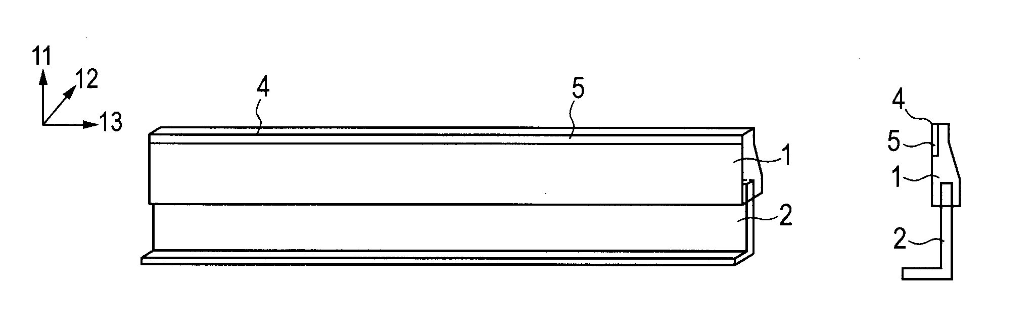
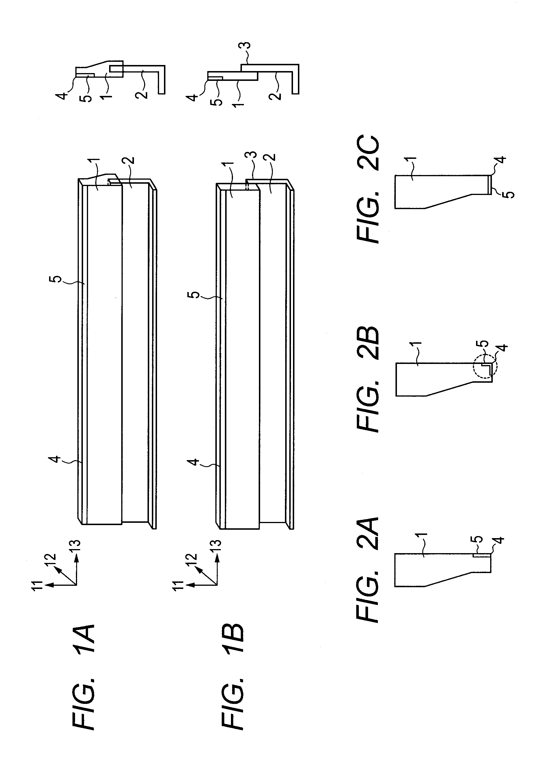
[0066]326.3 g of MDI was reacted with 673.7 g of PBA at 80° C. for 3 hours to obtain a prepolymer having an NCO % of 8.50%. To the prepolymer, 198.4 g of a curing agent prepared by adding 26.2 g of 14BD, 21.4 g of TMP, 0.07 g of the catalyst A and 0.28 g of the catalyst B to 150.8 g of PHA was blended to prepare a polyurethane elastomer raw material composition for a blade member. The obtained mixture was poured into a metal mold for molding a cleaning blade in which the supporting member was disposed with the adhesive applied portion being protruded within the cavity, and cured at 130° C. for 2 minutes. Then, the obtained product was removed from the metal mold to obtain a cleaning blade before impregnation with the isocyanate compound. The blade member had a blade free length direction 11 of 240 mm, a blade thickness direction 12 of 15 mm (in the edge of the image bearing member contact region) and a blade longitudinal direction 13 of 2...

example 1

[0067]To the surface of the contact region of the blade member of the cleaning blade to contact the image bearing member before impregnation with the isocyanate compound produced above, application of and impregnation with the modified MDI as the isocyanate compound were performed at a width of 5 mm from the contact edge under an environment of 25° C., and left and aged under an environment of 23° C. / 55 RH % for 3 hours. Subsequently, in order to provide edge properties in the contact region of the blade member to contact the image bearing member, the obtained blade member was cut by 2 mm, and a cleaning blade for an electrophotographic apparatus treated with the isocyanate compound was produced as illustrated in FIG. 1A. The number of moles of isocyanate was calculated from the amount of the isocyanate compound to be applied, and the concentration of an isocyanate group per unit area was calculated. The number of moles was 41.7×10⁻⁵ mmol / mm2.

[0068]The obtained cleaning blade was ev...

example 2

[0085]The isocyanate compound was diluted by a solvent MIBK such that the concentration of the isocyanate compound was 50 wt %, and after that, a cleaning blade was produced in the same manner as in Example 1. The concentration of an isocyanate group per unit area at this time was 5.6×10⁻⁵ mmol / mm2. The viscosity of the isocyanate compound solution was 4 mPa·s, and the contact angle to the non-treated blade member was 27°.

[0086]The concentrations of nitrogen in the blade member were as follows:

N0: 7.2 wt %, N5: 3.3 wt %, Ne: 1.3 wt %; and

Δ1=N0−N5=3.9 wt %, Δ2=N5−Ne=2.0 wt %.

[0087]As the hardness of the blade member, the hardness in the portion treated with the isocyanate compound Ha was 72.5 IRHD, that in the portion not treated with the isocyanate compound Hb was 72.0 IRHD, and the difference was 0.5 IRHD. The portion treated with the isocyanate compound had a roughness Rzjis of 0.8 μm and a friction coefficient of 0.5. Further, as a result of evaluation using the printer above, no...


PUM

PropertyMeasurementUnit
concentrationaaaaaaaaaa
hardnessaaaaaaaaaa
plastic deformationaaaaaaaaaa

Abstract

A cleaning blade for an electrophotographic apparatus including a thermosetting polyurethane elastomer blade member, in which in the blade member, a concentration of nitrogen is gradually increased from an inside of a contact region to contact the image bearing member toward the surface of the contact region; and a relationship between an amount of the concentration of nitrogen to be changed Δ1=N0−N5 and an amount of the concentration of nitrogen to be changed Δ2=N5−Ne is Δ1>Δ2 wherein a concentration of nitrogen in the surface N0 is not less than 1.5 wt % and not more than 20.0 wt %, a concentration of nitrogen Ne at a depth in which the concentration of nitrogen is no longer changed is not less than 0.7 wt % and not more than 10 wt %, and N5 is a concentration of nitrogen at a depth of 5 μm.

Description

BACKGROUND OF THE INVENTION[0001]1. Field of the Invention[0002]The present invention relates to a cleaning blade for an electrophotographic apparatus used to remove a remaining toner on image bearing members such as a photoreceptor drum, a transfer belt, and an intermediate transfer member, which are used in an electrophotographic apparatus.[0003]2. Description of the Related Art[0004]In an electrophotographic apparatus, a variety of cleaning blades are disposed in order to remove a remaining toner on image bearing members such as a photoreceptor drum, a transfer belt, and an intermediate transfer member. Blade members of these cleaning blades are mainly formed with a thermosetting polyurethane elastomer from the viewpoint of plastic deformation and resistance to wear.[0005]Recently, a demand for high quality images has been increased, leading to a more spherical form of a toner with a smaller particle size. For this reason, higher cleaning performance has been demanded of the clea...

Claims


Application Information

Patent Timeline
Patent Type & Authority Applications(United States)
IPC IPC(8): G03G21/00B32B27/40
CPCG03G21/0017Y10T428/31551G03G21/00
Inventor UEMATSU, ERIKAYAMAMOTO, ARIHIROINOUE, SYOUJI
Owner CANON KK
Why Eureka
Try Eureka