Supercharge Your Innovation With Domain-Expert AI Agents!

Concrete trowel transport system

a technology of transport system and finishing machine, which is applied in the direction of roads, vehicle maintenance, roads, etc., can solve the problems of green concrete not being able to support heavy machinery for several weeks after moving the trowel, the weight of the machine is also detrimental to the non-use transportation of the trowel, and the machine is unable to move the trowel. to achieve the effect of not substantially increasing the weight of the finishing machine and being easy to opera

Active Publication Date: 2012-06-28
HUSQVARNA AB
View PDF0 Cites 1 Cited by
  • Summary
  • Abstract
  • Description
  • Claims
  • Application Information

AI Technical Summary

Benefits of technology

[0020]Another aspect of the invention is to provide a power concrete finishing trowel that meets the first principal aspect and that is simple to operate, does not substantially increase the weight of the finishing machine, and is inexpensive.

Problems solved by technology

Although the weight of the machine can be beneficial for providing efficient, robust, and powerful trowel operation, the weight of the machine is also detrimental to non-use transportation of the trowel, i.e. while moving the trowel within the worksite or to or from a worksite without operating the blades.
These machines experience difficulty in moving the trowel in certain work environments.
For instance, for large slab on grade jobs where a number of pours are required to complete a floor, the green concrete is unable to support the heavy machinery for several weeks after a pour.
Forklifts and similar devices therefore cannot access the trowels for transport.
For instance, some known trowels may weigh as much as 2800 pounds, making the prior art transport systems unsuitable for use therewith.
This is a labor intensive and physically demanding technique for moving such machines.
Although such systems enhance the mobility of power trowels, they are not without their drawbacks.
For instance, because the wheel assemblies of the Allen '323 patent are located outboard of the cage, they increase the overall footprint of the machine.
Increasing the footprint of the machine increases the space occupied by the machine.
This limitation is problematic because users of finishing machines prefer that the machine finish as much of the pour area as possible.
The areas that cannot be finished due to the interference between the wheel assemblies and the obstructions must be finished by hand, increasing the amount of hand work associated with a given pour.
Transport systems such as the one disclosed in U.S. Pat. No. 5,238,323 are also relatively inefficient.
In addition, unless care is taken to operate both jacks the same amount, one side of the machine may be higher than the other during transport, reducing the stability and maneuverability of the machine.
Like any accessory, these wheel kits are susceptible to being lost, left behind, or damaged at job sites because they are set aside when not in use.
While the device of the '139 patent is thus an improvement over the '323 patent, the presence of even a single jack may prove to be cumbersome during maintenance of the trowel.
Manually operating a jack also is labor intensive.
The need to manually actuate the jack or other lifting mechanisms of traditional wheel kits is especially problematic with large, hydraulically powered trowels.
This dramatic difference in weight renders traditional manually actuated jacks and their associated wheel kit components ill-suited for use with hydraulically powered trowels.

Method used


Image

  • Concrete trowel transport system
  • Concrete trowel transport system
  • Concrete trowel transport system

Examples


Embodiment Construction

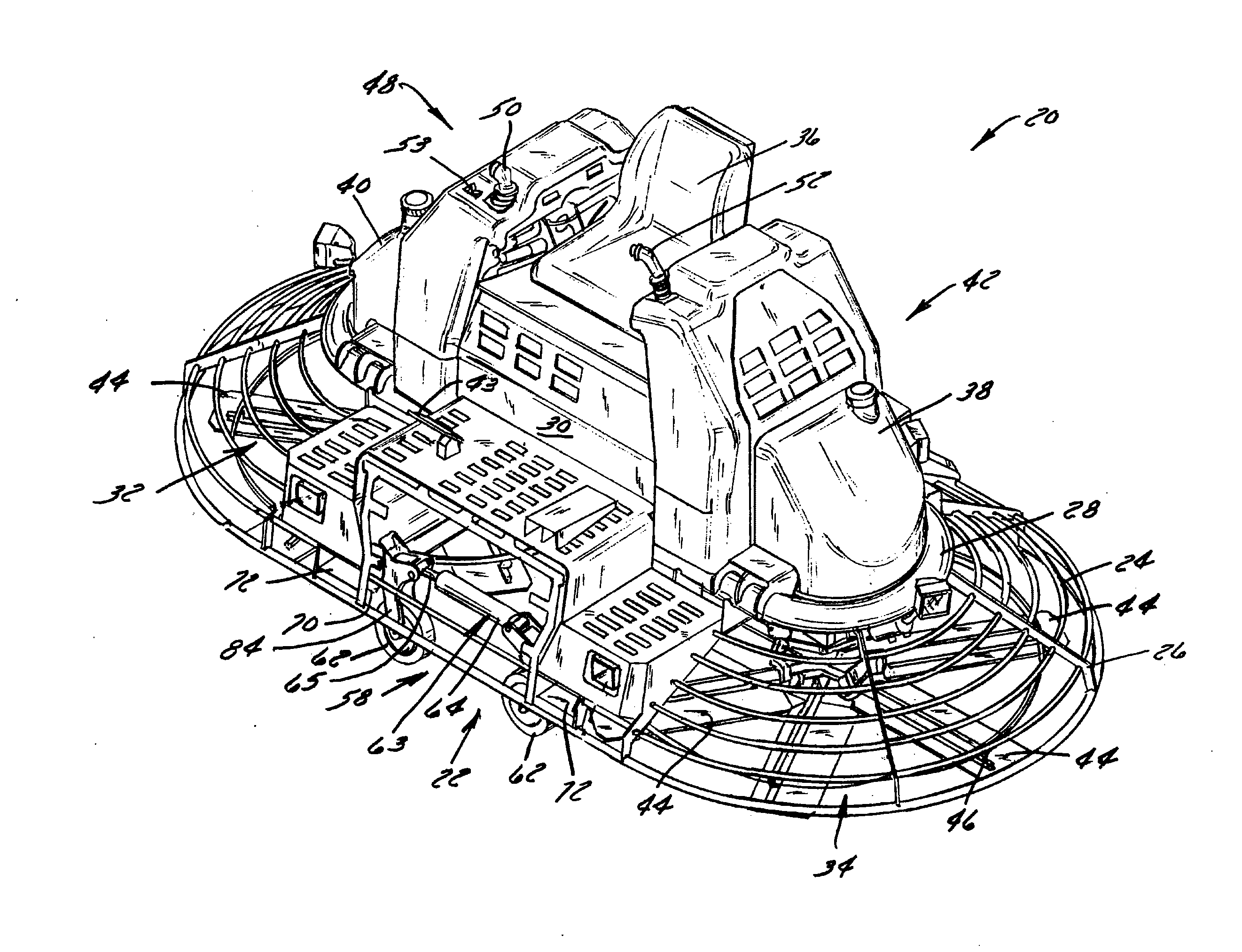
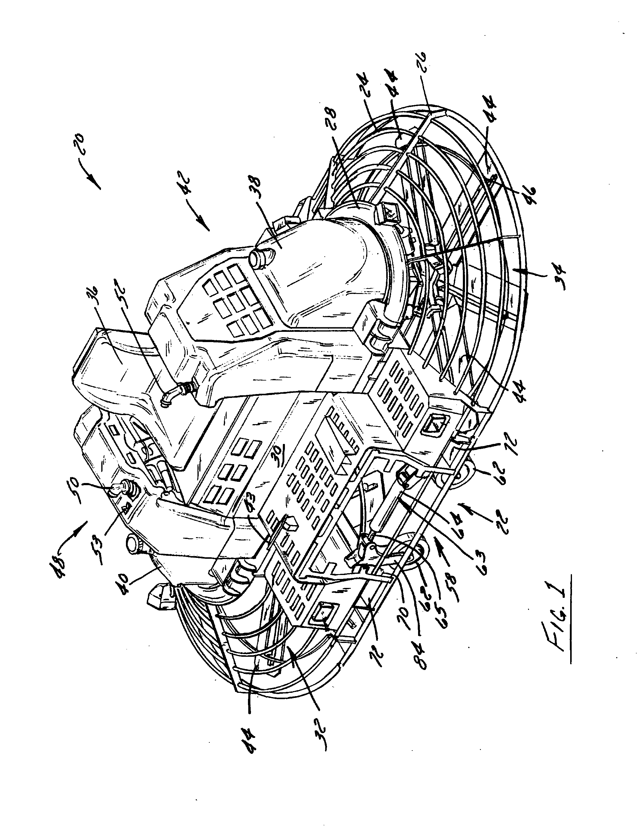
[0033]FIG. 1 shows a self-propelled riding concrete finishing trowel 20 equipped with a transport system 22 that is constructed according to a preferred embodiment of the present invention and that is positioned nearly entirely beneath the shroud or cage 24 of the trowel 20. Although shown as what is commonly understood as a riding or ride-on trowel, it is appreciated that the present invention is applicable to any powered concrete finishing trowel that cannot easily be manually moved by an operator without substantial physical effort. That is, it is conceivable that riding power trowels having configurations other than that shown, or even walk-behind trowels, could be equipped with a transport system according to the present invention.

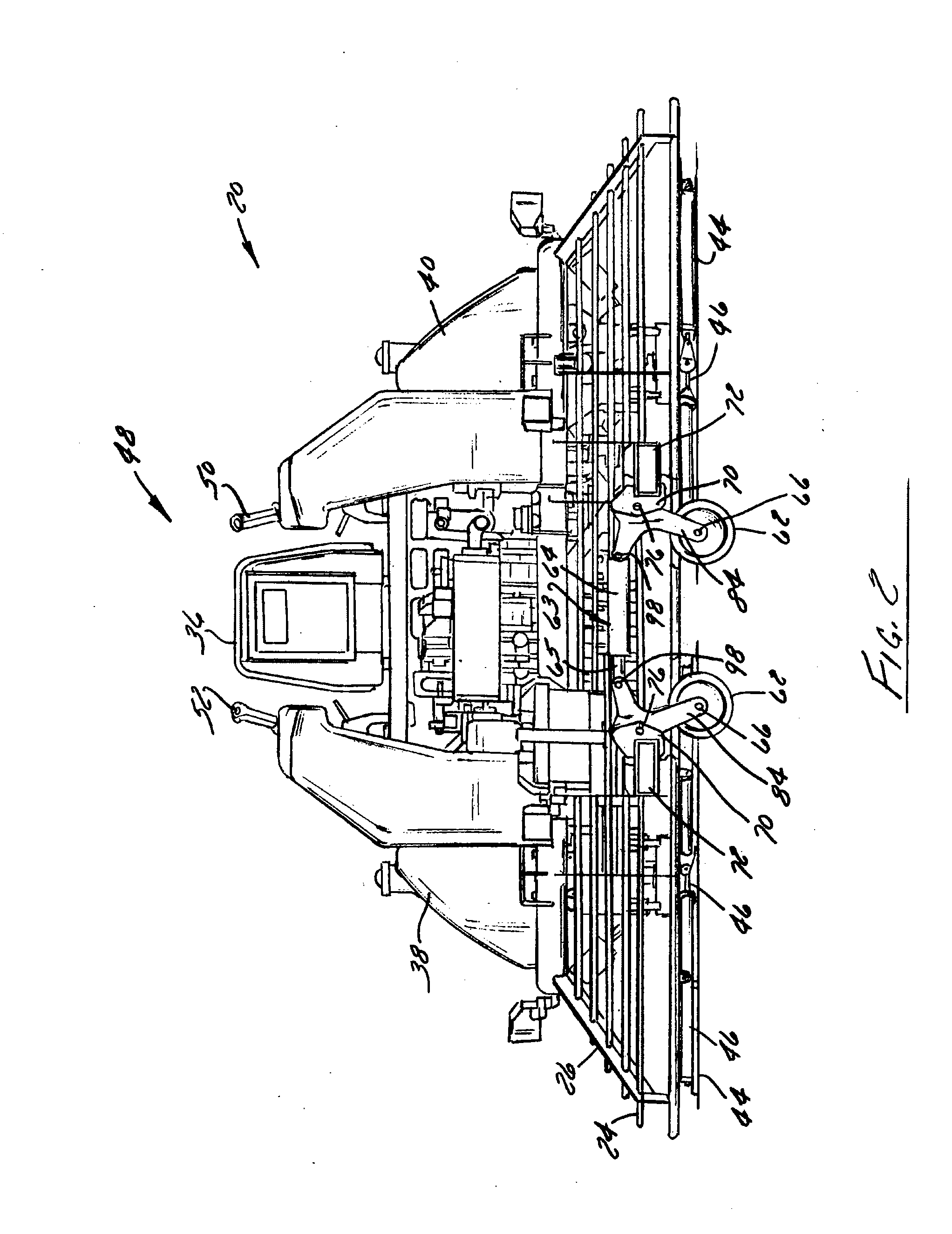
[0034]Referring to FIGS. 1-3, and initially to FIG. 1 in particular, concrete finishing trowel 20 in accordance with a preferred embodiment of the invention includes as its major components a rigid metallic frame 26, an upper deck 28 mounted on frame ...


PUM


Abstract

A self-propelled concrete finishing trowel has an integrated transport system that allows the towel to be moved from location to location. The transport system includes a pair of spaced wheel assemblies, each including a pair of wheels that are connected to a frame of the trowel. The wheels of each respective wheel assembly are connected to one another via a powered actuator such as a double acting hydraulic cylinder. The powered actuator is actuatable to raise and lower the first and second wheels from a stowed position in which the wheels are located above the ground and the blades are supported on the ground to a deployed position in which the wheel are supported on the ground and the blades are raised from the ground.

Description

BACKGROUND OF THE INVENTION[0001]1. Field of the Invention[0002]The invention relates generally to concrete finishing trowels and, more particularly, to a transport system for a powered finishing trowel. The invention additionally relates to a concrete finishing trowel, such as a riding trowel, having an integrated transport system that enables wheeled transport of the trowel within a worksite and to and from a worksite.[0003]2. Description of the Related Art[0004]A variety of machines are available for smoothing or otherwise finishing wet concrete. These machines range from simple hand trowels, to walk-behind trowels, to self-propelled riding trowels. Regardless of the mode of operation of such trowels, the powered trowels generally include one to three rotor assemblies that rotate relative to the concrete surface.[0005]Riding concrete finishing trowels can finish large sections of concrete more rapidly and efficiently than manually pushed or guided hand-held or walk behind finishi...

Claims


Application Information

Patent Timeline
IPC IPC(8): B60S9/02E01C19/22
CPCE04F21/247E04F21/245E04F21/248
Inventor LICKEL, TIMOTHY J.GRAHL, SCOTT
Owner HUSQVARNA AB
Features
  • R&D
  • Intellectual Property
  • Life Sciences
  • Materials
  • Tech Scout
  • Unparalleled Data Quality
  • Higher Quality Content
  • 60% Fewer Hallucinations
Learn More