
Device for clamping and rotating the object

a technology for clamping and rotating objects, applied in the direction of conveyor parts, transportation and packaging, manufacturing tools, etc., can solve the problems of inconvenient use, and achieve the effect of reducing the volume of the devi

Inactive Publication Date: 2012-06-28
CHAN LI MACHINERY
View PDF11 Cites 29 Cited by
  • Summary
  • Abstract
  • Description
  • Claims
  • Application Information

AI Technical Summary

Benefits of technology

[0015]It is still another object of the present invention to provide a device for clamping and rotating the object, wherein the first rod is positioned within a through hole of the second rod, and the third rod is positioned within a through hole of the fourth rod, such that the first rod and the second rod can be rotated independently, and the third rod and the fourth rod can be rotated independently, besides, the volume of the device can be reduced.

Problems solved by technology

Accordingly, it is inconvenient for use.

Method used


Image

  • Device for clamping and rotating the object
  • Device for clamping and rotating the object
  • Device for clamping and rotating the object

Examples


first embodiment

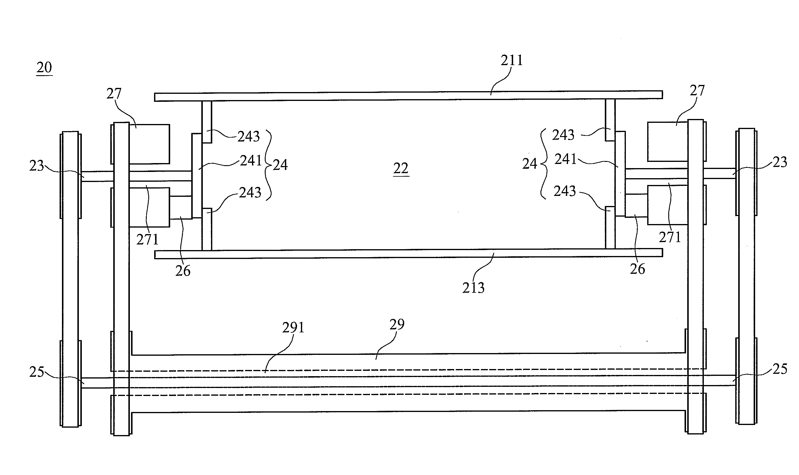
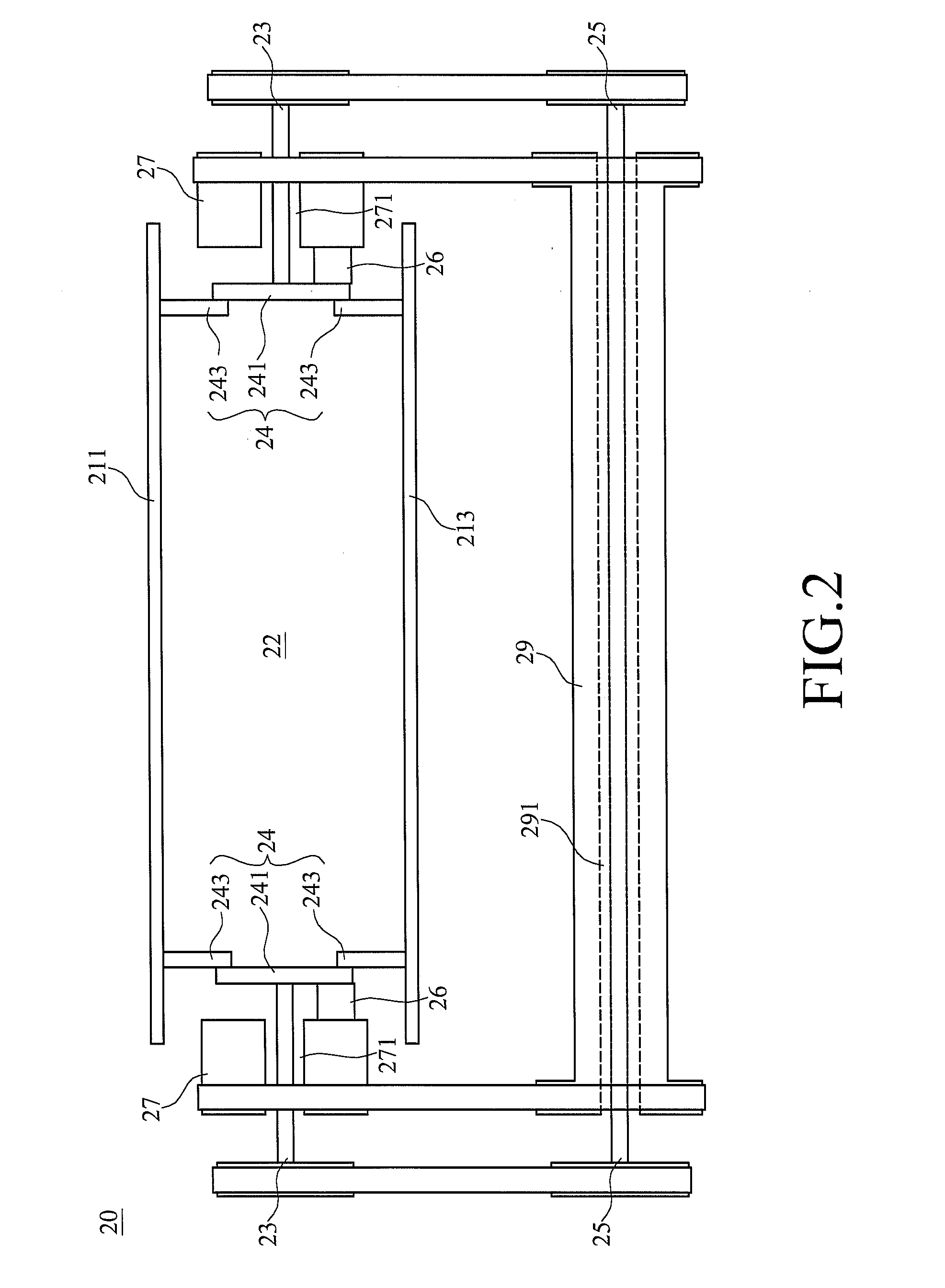
[0034]Please refer to FIG. 2, a device for clamping and rotating the object in accordance with the present invention is shown. The device 20 comprises a first plate 211, a second plate 213, two first rods 23, two linked units 24, two second rods 27, a third rod 25, and a fourth rod 29. The first plate 211 is placed in the opposite position of the second plate 213, and a clamping space 22 is provided between the first plate 211 and the second plate 213. The object, such as the stacked web products, can be placed in the clamping space 22, for being clamped and rotated through the first plate 211 and the second plate 213.

[0035]Two linked units 24 respectively comprise a rotating unit 241 and two connecting units 243, wherein the rotating unit 241 is connected to the first plate 211 and the second plate 213 respectively through two connecting units 243. The rotating unit 241 rotates to drive the first plate 211 and the second plate 213 through two connecting units 243, such that the fir...

third embodiment

[0043]Referring to FIG. 5, a device for clamping and rotating the object in accordance with the present invention is shown. The device 30 comprises a first plate 211, a second plate 213, two first rods 23, two linked units 24, two second rods 27, a third rod 25, and a fourth rod 29.

[0044]The first rods 23 are connected to the first plate 211 and the second plate 213 respectively through the linked units 24, wherein each of the linked units 24 comprises a rotating unit 241 and two connecting units 243. The first rods 23 are connected to the rotating units 241, and the rotating units 241 are respectively connected to the first plate 211 and the second plate 213 through two connecting units 243. The first plate 211 and the second plate 213 are drove to displace up and down for altering the size of clamping space 22 between the first plate 211 and the second plate 213 by the rotating units 241 through the connecting units 243, wherein the rotating units 241 are drove to rotate by the fi...


PUM

PropertyMeasurementUnit
Timeaaaaaaaaaa
Heightaaaaaaaaaa

Abstract

A device, used for clamping and rotating the object, includes two first rods, one ends of which are respectively connected to one ends of the first plate and the second plate through a linked unit; another ends of the first rods are connected to the third rod that is used for balancing the rotating angles of the first rod and two linked units, such that the heights of two ends of the first rods and the second rods can be kept in step. Two second rods are connected to the first plate and the second plate respectively, as well as, another ends of second rods are connected to the fourth rod respectively. Accordingly, the fourth rod can be rotated to drive the second rod, such that the first plate and the second plate can be rotated. Therefore, due to two plates are used for clamping and rotating synchronously, users can take the advantages while the device is used.

Description

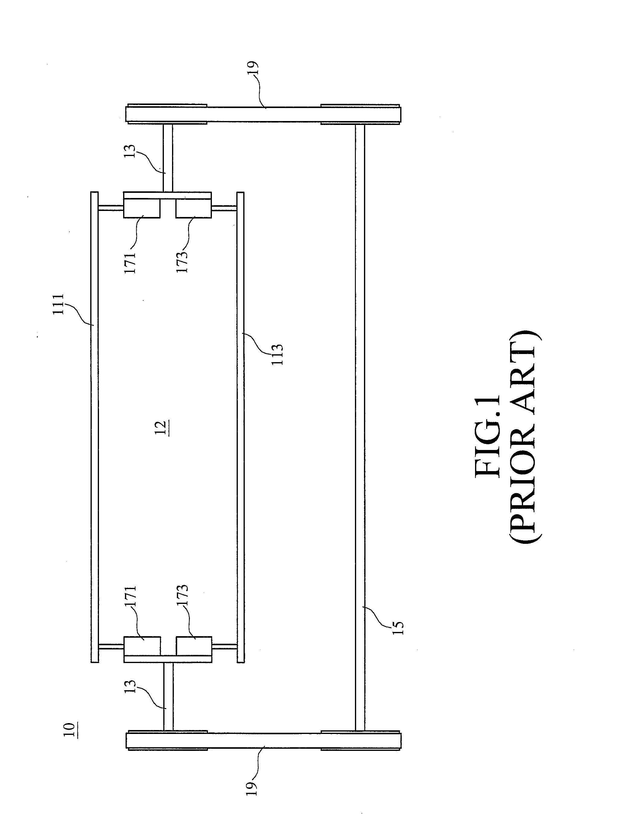
BACKGROUND OF THE INVENTION[0001]1. Technical Field[0002]The present invention relates to a device for clamping and rotating the object, comprising two plates to be opened and closed or rotated over synchronously.[0003]2. Description of the Prior Art[0004]FIG. 1 illustrates a device for clamping and rotating the object according to the prior art. As illustrated, the device 10 comprises a first plate 111, a second plate 113, two first rods 13, and a second rod 15. The first plate 111 is positioned oppositely with the second plate 113, and a clamping space 12 is provided between the first plate 111 and the second plate 113.[0005]Two first rods 13 are provided on two ends of the first plate 111 and the second plate 113 respectively, that is, one ends of the first rods 13 are respectively connected to the first plate 111 and the second plate 113 through the first cylinder 171 and second cylinder 173. Accordingly, the first plate 111 and the second plate 113 can be drove to displace up a...

Claims


Application Information

Patent Timeline
IPC IPC(8): B65G47/24
CPCB65G47/24
Inventor HSU, HUANG-PIN
Owner CHAN LI MACHINERY
Learn More