Radiant Burner

a burner and radiant technology, applied in the direction of burners, burner types, burner material specifications, etc., can solve the problems of only weak and inefficient heating of materials, flame going out,

Inactive Publication Date: 2012-06-28
SANDVIK INTELLECTUAL PROPERTY AB
View PDF11 Cites 55 Cited by
  • Summary
  • Abstract
  • Description
  • Claims
  • Application Information

AI Technical Summary

Problems solved by technology

If the flames burn as individual flames over the burner plate, the material is heated only weakly and inefficiently.
The described design has the disadvantage that, if a high fuel gas throughflow for a high radiant power and burner temp

Method used


Image

  • Radiant Burner
  • Radiant Burner
  • Radiant Burner

Examples


Embodiment Construction

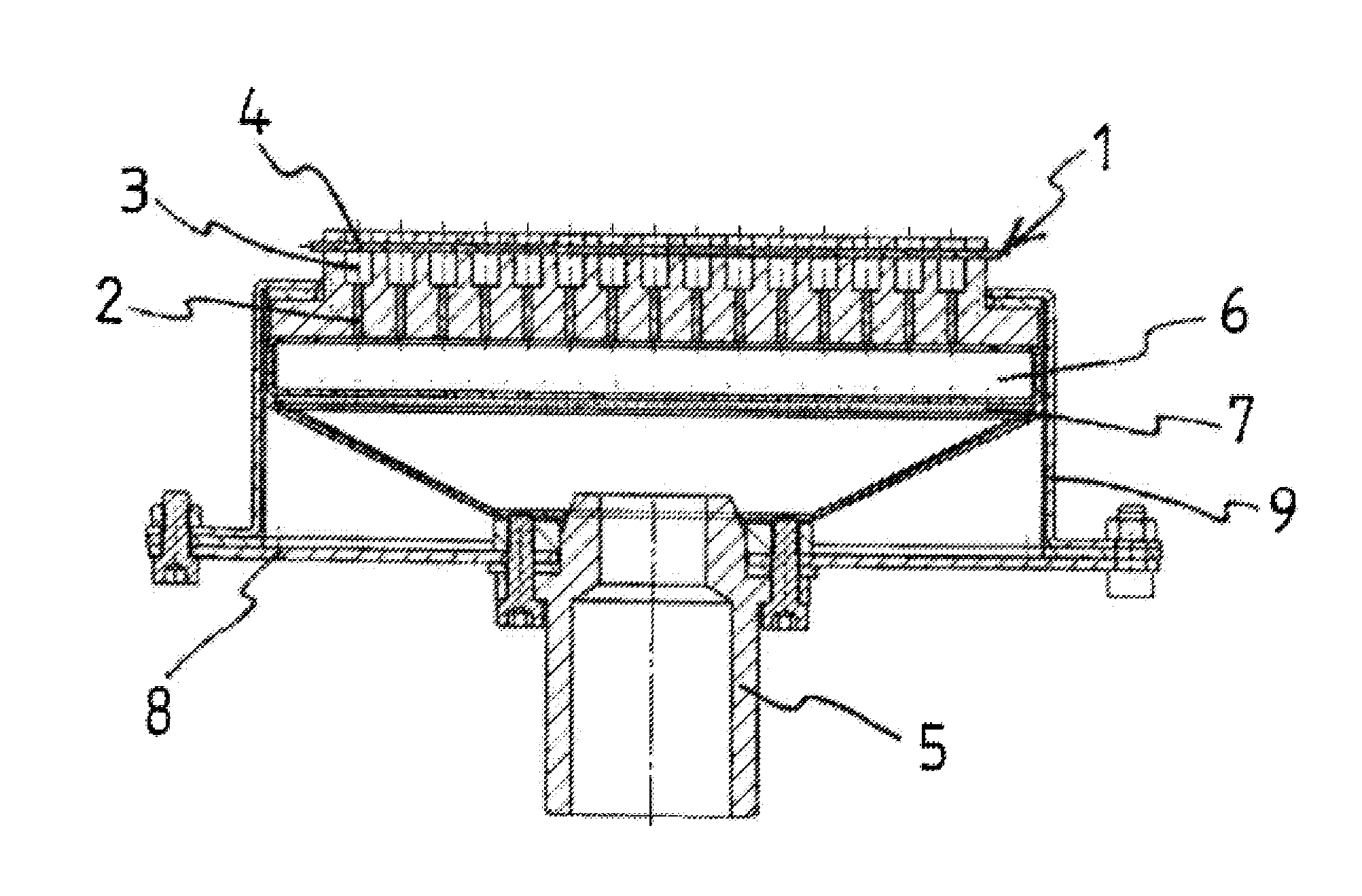
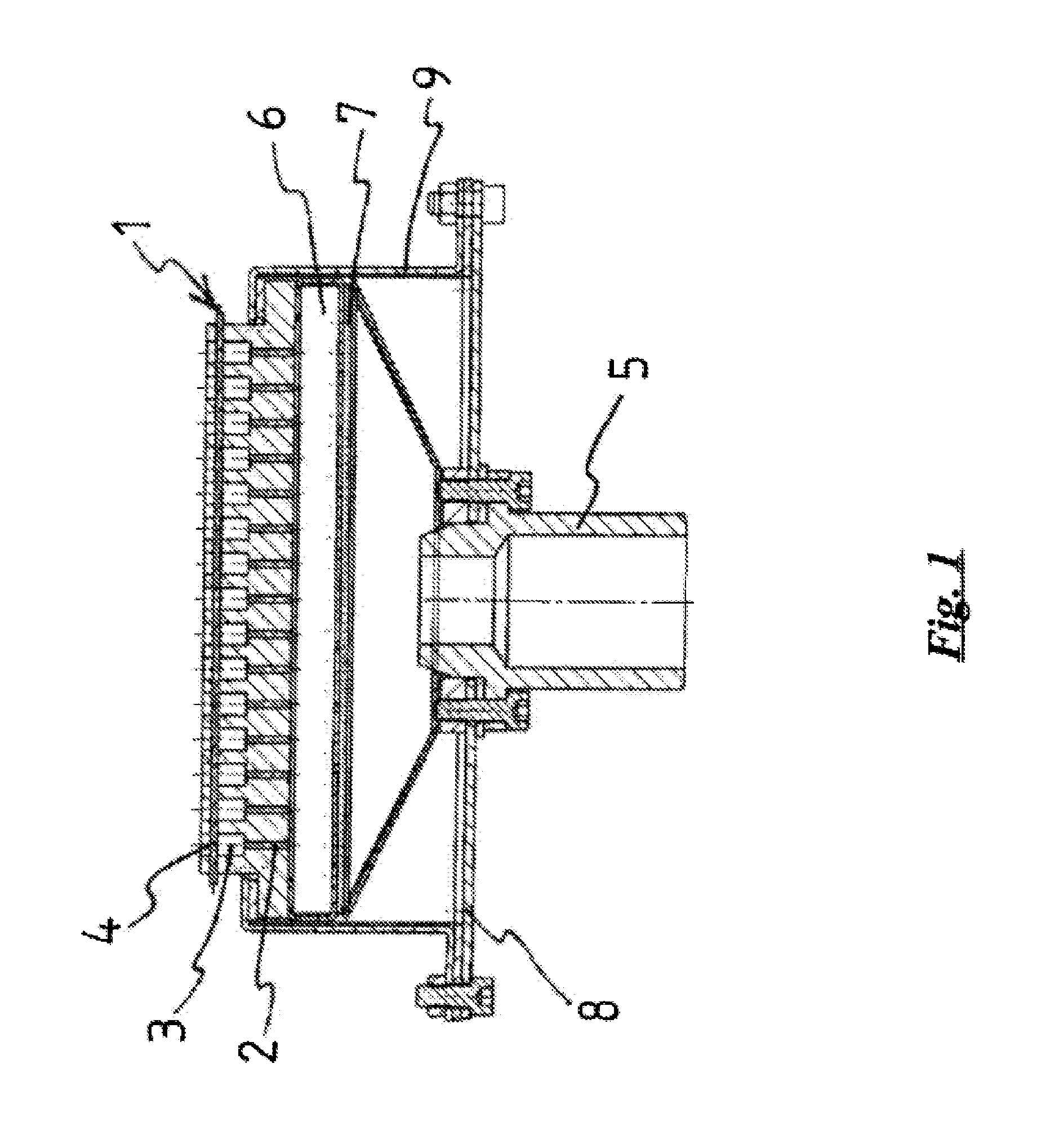
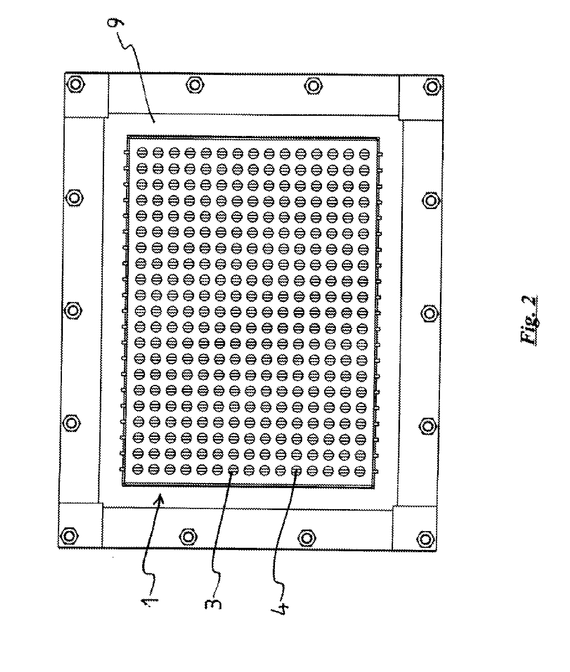
[0009]The object according to the invention is achieved by a burner, in particular a radiant burner, for the combustion of a gas mixture of fuel gas and an oxygen carrier gas, with a burner plate with passage channels for the throughflow of the gas mixture from a mixing chamber side to a combustion side, wherein, on the combustion side, combustion channels with an enlarged cross-section compared with the passage channels connect to the passage channels and flow obstacles are arranged in the combustion channels for a contact with the combustion flame, wherein the flow obstacles are made of a material which has a higher thermal conductivity than the material of the burner plate.

[0010]In one embodiment of the burner according to the invention, the passage channels for the throughflow of the gas mixture have at least one point over their length a maximum diameter which is smaller than the quenching distance of the combustion.

[0011]The term “maximum diameter” within the meaning of the pr...


PUM


Abstract

The invention relates to a burner, in particular a radiant burner, for the combustion of a gas mixture of fuel gas and an oxygen carrier gas, with a burner plate with passage channels for the throughflow of the gas mixture from a mixing chamber side to a combustion side, wherein, on the combustion side, combustion channels with an enlarged cross-section compared with the passage channels connect to the passage channels, wherein flow obstacles for a contact with the combustion flame are arranged in the combustion channels and the flow obstacles are made of a material which has a higher thermal conductivity than the material of the burner plate.

Description

SUBJECT OF THE INVENTION[0001]The invention relates to burners, in particular a radiant burner, for the combustion of a gas mixture of fuel gas and an oxygen carrier gas. The burner has a burner plate with passage channels for the throughflow of the gas mixture from a mixing chamber side to a combustion side. On the combustion side, combustion channels with an enlarged cross-section compared with the passage channels connect to the passage channels.BACKGROUND OF THE INVENTION[0002]Radiant burners or surface burners of the type according to the preamble have a mixing chamber in which a gas mixture of fuel gas and an oxygen carrier gas is produced. Connected to the mixing chamber is a burner plate with passage channels through which the gas mixture flows out of the mixing chamber and is burned.[0003]The passage channels in the burner plate for the throughflow of the gas mixture from the mixing chamber side to a combustion side are so narrow that the individual flames forming on the ex...

Claims


Application Information

Patent Timeline
IPC IPC(8): F23D14/14
CPCF23D14/145F23D14/58F23D14/82F23D2900/00003F23D2212/10F23D2212/20F23D2203/1023
Inventor MACH, ALEXANDER
Owner SANDVIK INTELLECTUAL PROPERTY AB
Why Eureka
Try Eureka